Seismic imaging apparatus utilizing macro-velocity model and method for the same

a micro-velocity model and seismic imaging technology, applied in seismic imaging, instruments, measurement devices, etc., can solve the problems of noise appearing in laplace-domain inversion, use of two-step inversion process, and difficulty in recovering accurate velocity models from field data or even synthetic data, etc., to achieve enhanced resolution and reduce computation. the effect of the amount o

Active Publication Date: 2012-09-27
SEOUL NAT UNIV R&DB FOUND
View PDF9 Cites 33 Cited by
  • Summary
  • Abstract
  • Description
  • Claims
  • Application Information

AI Technical Summary

Benefits of technology

[0006]The following description relates to a technique of reducing the amount of computat...

Problems solved by technology

However, recovering an accurate velocity model from field data or even synthetic data can be difficult due to local minima in the objective functions and the absence of low-freque...

Method used


Image

  • Seismic imaging apparatus utilizing macro-velocity model and method for the same
  • Seismic imaging apparatus utilizing macro-velocity model and method for the same
  • Seismic imaging apparatus utilizing macro-velocity model and method for the same

Examples


Embodiment Construction

[0018]The following description is provided to assist the reader in gaining a comprehensive understanding of the methods, apparatuses, and / or systems described herein. Accordingly, various changes, modifications, and equivalents of the methods, apparatuses, and / or systems described herein will be suggested to those of ordinary skill in the art. Also, descriptions of well-known functions and constructions may be omitted for increased clarity and conciseness.

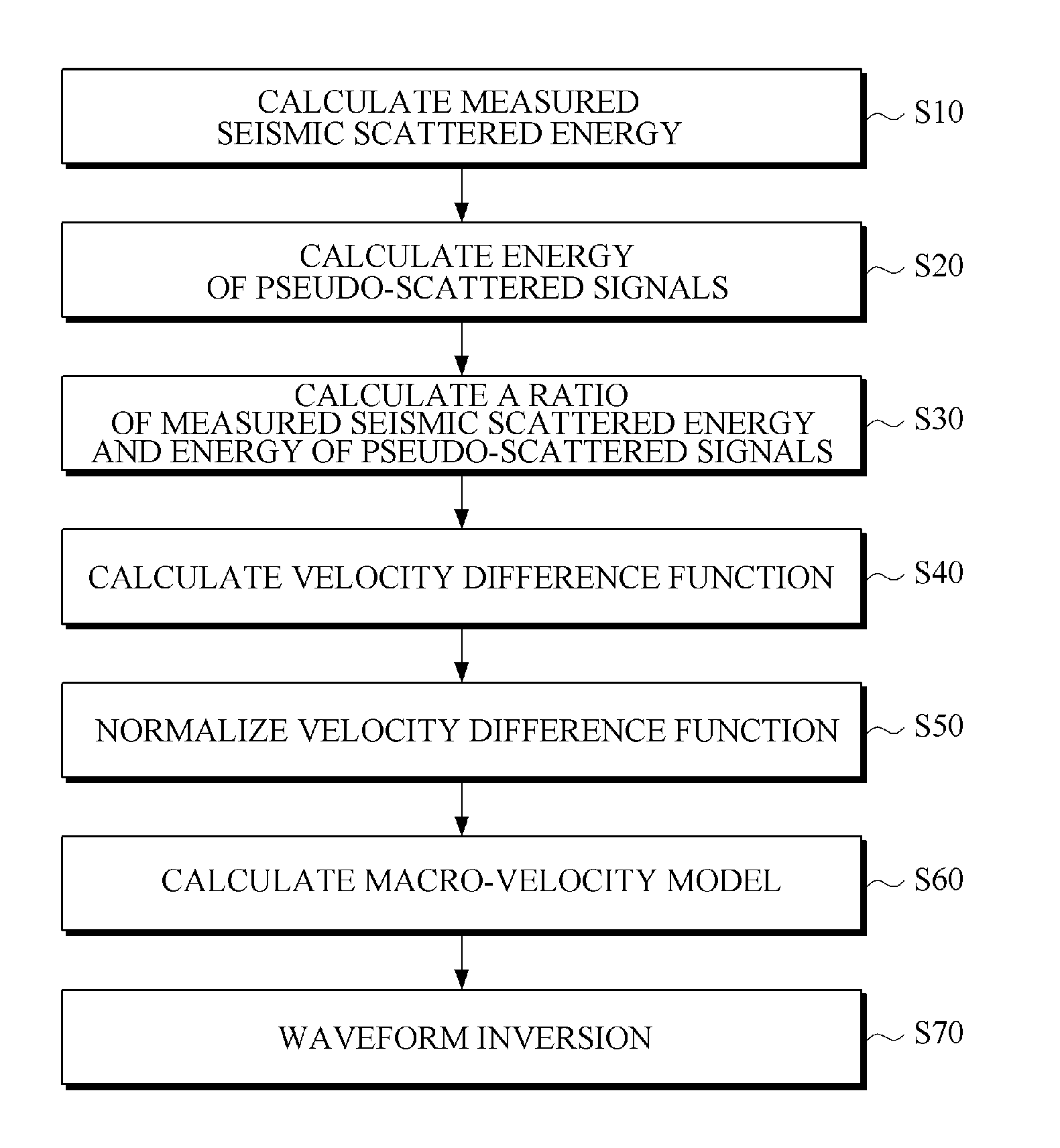
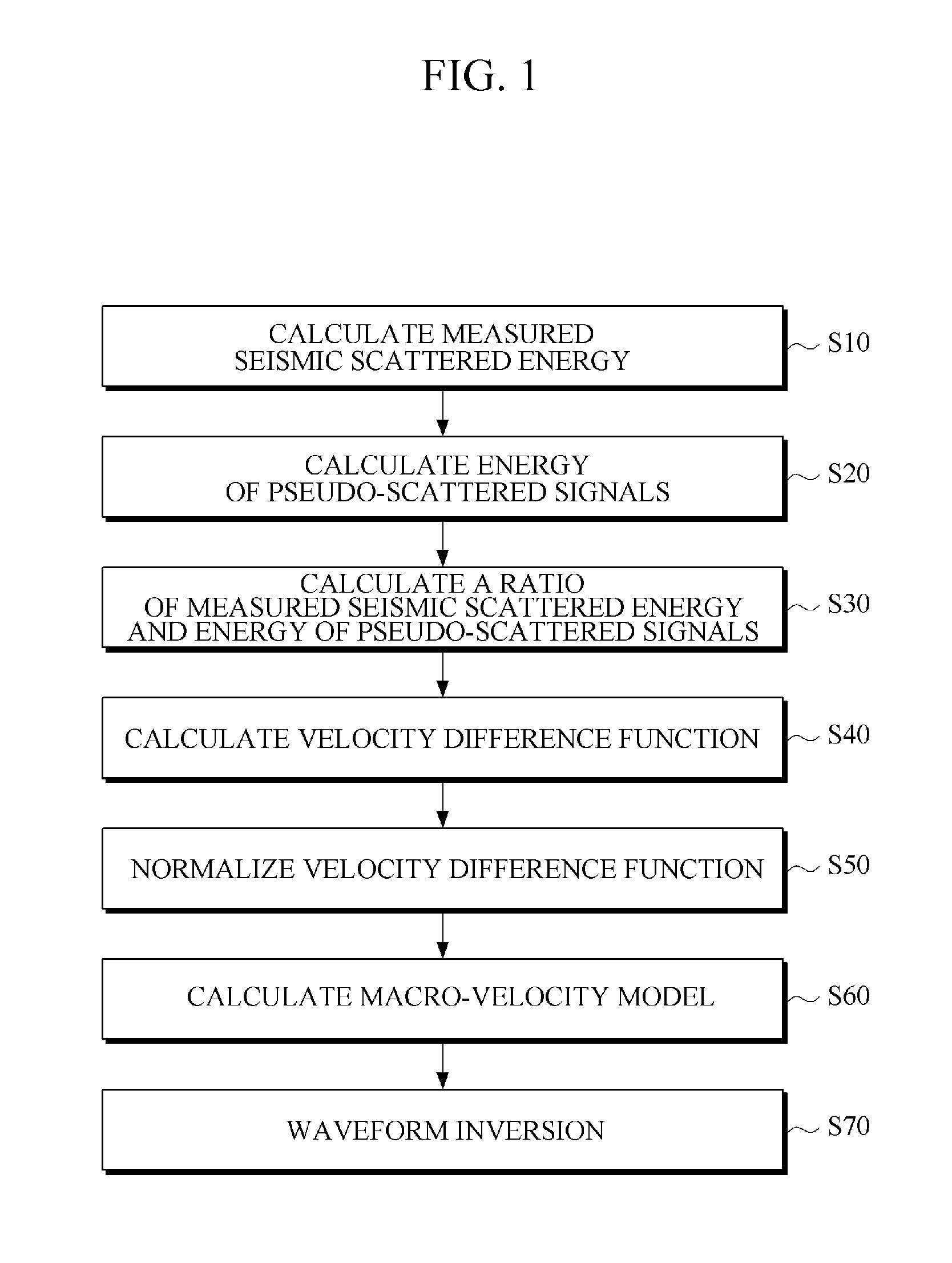
[0019]FIG. 1 is a schematic flow diagram illustrating an example of a seismic imaging method for obtaining imaging data of a subsurface structure through waveform inversion using a macro-velocity model as an initial value. The macro-velocity model is used as an initial value for the waveform inversion. As shown in FIG. 1, the macro-velocity model is calculated by calculating a velocity difference function (S40) which is a difference between a real velocity and an initial velocity model, wherein the velocity difference function is ...


PUM


Abstract

There is provided a seismic imaging technology for imaging a subsurface structure by processing measured data reflected from the subsurface structure after a wave from a source wave has been propagated to the subsurface structure. According to an aspect, there is provided a seismic imaging method for obtaining imaging data of a subsurface structure through waveform inversion using a macro-velocity model as an initial value, wherein the macro-velocity model which is used as the initial value for the waveform inversion is calculated by: calculating a velocity difference function which is a difference between a real velocity and an initial velocity model, wherein the velocity difference function is a ratio of measured seismic scattered energy and modeled scattered energy based on the initial velocity model; and calculating the macro-velocity model by updating the initial velocity model with the velocity difference function.

Description

CROSS-REFERENCE TO RELATED APPLICATION[0001]This application claims the benefit under 35 U.S.C. §119(a) of a U.S. Patent Application No. 61 / 466,333, filed on Mar. 22, 2011, and a Korean Patent Application No. 10-2012-0029031, filed on Mar. 21, 2012, the entire disclosures of which are incorporated herein by reference for all purposes.BACKGROUND[0002]1. Field[0003]The following description relates to a seismic imaging technology for imaging a subsurface structure by processing measured data reflected from the subsurface structure after a is wave from a source wave has been propagated to the subsurface structure.[0004]2. Description of the Related Art[0005]Geophysicists study subsurface structures using information recorded at the surface in various ways, one of which is a full waveform inversion. However, recovering an accurate velocity model from field data or even synthetic data can be difficult due to local minima in the objective functions and the absence of low-frequency compone...

Claims


Application Information

Patent Timeline
IPC IPC(8): G01V1/28
CPCG01V2210/614G01V1/282G01V2210/622
Inventor SHIN, CHANGSOO
Owner SEOUL NAT UNIV R&DB FOUND
Why Eureka
Try Eureka