Battery case

a battery case and case body technology, applied in the field of battery cases, can solve the problems of low sealing functionality and failure to ensure the high sealing functionality of the case body, and achieve the effects of facilitating sealing, and suppressing the leakage of electrolyte solution

Active Publication Date: 2012-09-27
GS YUASA INT LTD
View PDF5 Cites 13 Cited by
  • Summary
  • Abstract
  • Description
  • Claims
  • Application Information

AI Technical Summary

Benefits of technology

[0006]The present invention has been contrived in order to address the above problem, and an object of the present invention is to provide a battery case having high sealing functionality.
[0008]According to the first aspect of the present invention, it is possible to ensure high sealing functionality by disposing the first sealing member and the second sealing member suitable for the respective portions of the joined portion where the plate sections overlap with each other, as compared to a case in which only one type of sealing member is used. Consequently, even in the case in which an electrolyte solution leaks from cells stored in the case, it is possible to effectively suppress leakage of the electrolyte solution from the battery case.
[0009]According to the first aspect of the present invention, preferably, the first sealing member is disposed between joining surfaces of the joined portion, and the second sealing member includes a paste sealing member, and is disposed so as to cover an end of the joining surface. By disposing the first sealing member between the joining surfaces and the paste second sealing member at the end of the joining surfaces, it is possible to seal the case at two positions: between the joining surfaces of the joined portion, and the end of the joining surfaces, and to improve the sealing functionality of the battery case.
[0011]According to the second aspect of the present invention, the battery case is provided by bending the plate member, the notch portions are each disposed at the end of the folded portion, and the closure-sealing member covering each of the notch portions is provided. With such a configuration, the notch portions are covered using the closure-sealing members, and even in the case in which the electrolyte solution leaks from the cells stored in the case, it is possible to effectively suppress leakage of the electrolyte solution from the battery case.
[0012]According to the first and the second aspects of the present invention, a gasket sealing member can be provided at an engaging portion between the battery case body and a cap body for covering an opening of the battery case body. With such a configuration,even when the removable cap body is provided, it is possible to facilitate the sealing between the battery case body and the cap body by the gasket sealing member. Therefore, even in the case in which the electrolyte solution leaks from the cells, it is possible to suppress leakage of the electrolyte solution through a portion between the battery case body and the cap body.

Problems solved by technology

In this case, as welding an aluminum material is difficult as compared to a material such as iron, a case body made of an aluminum material is often provided by jointing the material using fixation members such as rivets.
However, as compared to welding, forming a case body by jointing a material using fixation members is susceptible to gaps, and thus provides lower sealing functionality.
Consequently, a problem of failing to ensure high sealing functionality of the case body is envisaged.

Method used


Image

  • Battery case
  • Battery case
  • Battery case

Examples


Embodiment Construction

[0025]A preferred embodiment of the present invention will now be described hereinafter with reference to the drawings. First, a battery case 100 according to the embodiment will be described with reference to FIG. 1 to FIG. 6.

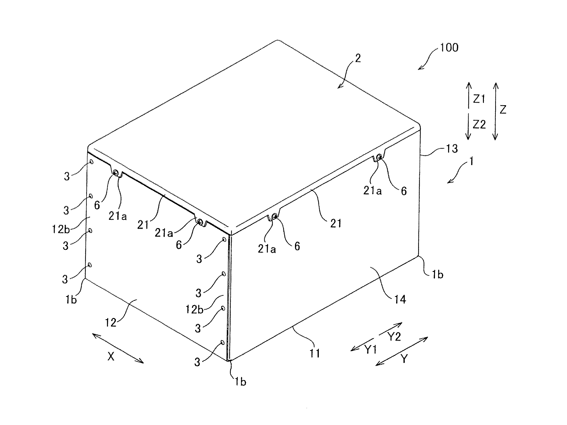
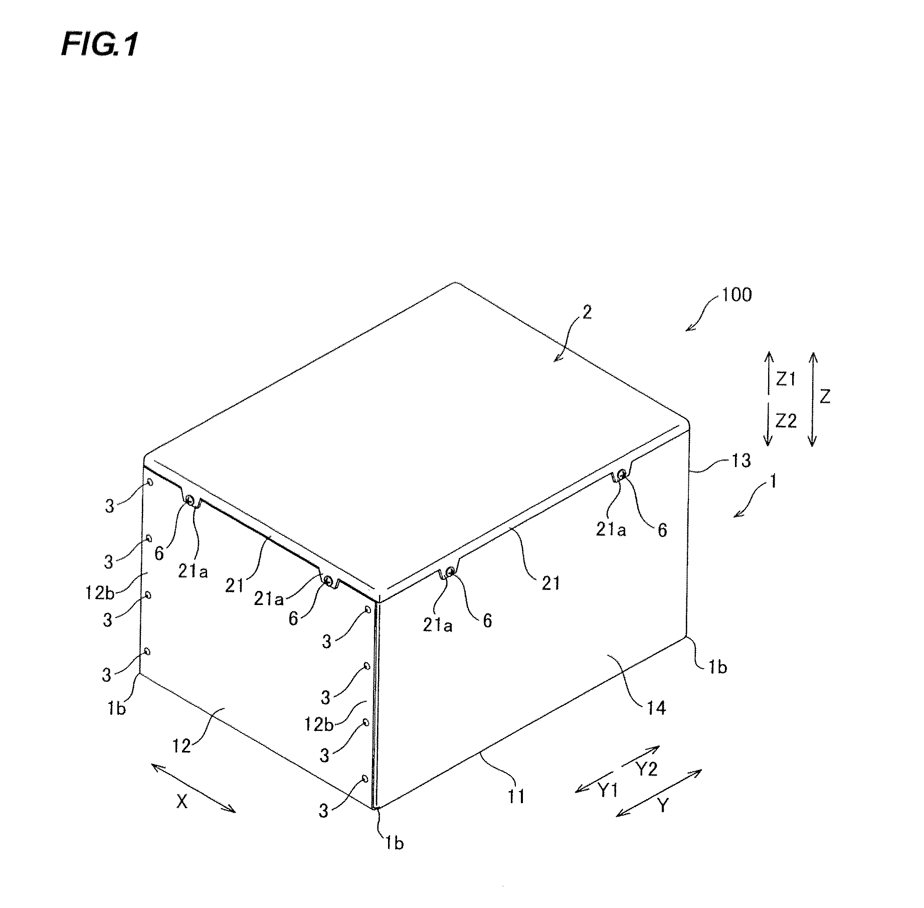
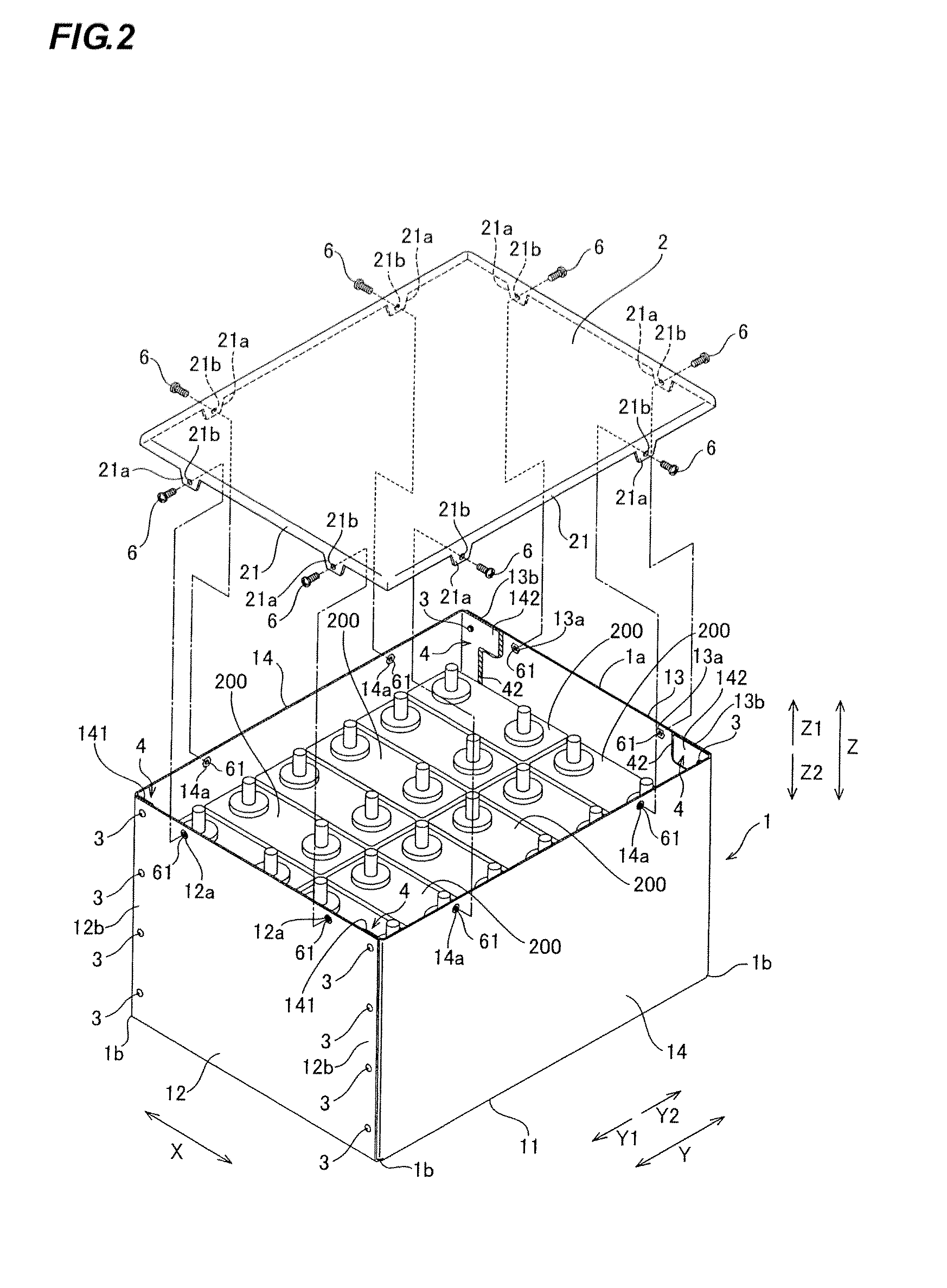
[0026]Referring to FIG. 1 and FIG. 2, the battery case 100 according to the embodiment is provided with a battery case body 1 in a box shape, and a cap body 2 covering an opening 1a of the battery case body 1.

[0027]The battery case body 1 is formed in the box shape by bending a plated material made of an aluminum alloy. It is possible to reduce the weight of the battery case 100 by using an aluminum alloy as the material of the battery case body 1. As illustrated in FIG. 1 and FIG. 2, the battery case body 1 includes a bottom section 11, and a front section 12, a back section 13, and two side sections 14 that are respectively coupled to four sides of the bottom section 11. The battery case body 1 stores twelve square-shaped lithium ion cells 200. In addition, ...


PUM

PropertyMeasurementUnit
weightaaaaaaaaaa
widthaaaaaaaaaa
resistanceaaaaaaaaaa

Abstract

The present invention provides a battery case configured by fixing a joined portion where plate sections overlap with each other using a fixation member, and two different types of sealing members are disposed at the joined portion. It is possible to ensure high sealing properties by using sealing members suitable for the respective shapes of portions of the joined portion.

Description

BACKGROUND OF THE INVENTION[0001]1. Field of the Invention[0002]The present invention relates to battery cases, and in particular, to a battery case having plate sections fixed to each other by a fixation member.[0003]2. Description of the Related Art[0004]JP-A-2007-200758 discloses a metal case (battery case) in which cells are stored. The metal case includes a case body (battery case body) and a cap plate (cap body) that are joined each other by screws, as well as a sealing member provided between the case body and the cap plate. Further, JP-A-2007-200758 also describes that the case body is made of a material such as iron or aluminum. In this case, as welding an aluminum material is difficult as compared to a material such as iron, a case body made of an aluminum material is often provided by jointing the material using fixation members such as rivets.[0005]However, as compared to welding, forming a case body by jointing a material using fixation members is susceptible to gaps, a...

Claims


Application Information

Patent Timeline
Patent Type & Authority Applications(United States)
IPC IPC(8): H01M2/02H01M50/262
CPCH01M2/1016H01M10/052H01M2/1094Y02E60/10H01M50/24H01M50/262
Inventor USHIJIMA, OSAMU
Owner GS YUASA INT LTD
Why Eureka
Try Eureka