Vehicular power transmitting system

a transmission system and transmission device technology, applied in the direction of vehicle sub-unit features, interengaging clutches, gearing, etc., can solve the problems of instability of the the risk of deterioration of the intended sealing function of the oil seal fitted on the piston, etc., to achieve increased operational reliability, efficient movement, and high stability

Active Publication Date: 2018-08-30
TOYOTA JIDOSHA KK
View PDF0 Cites 6 Cited by
  • Summary
  • Abstract
  • Description
  • Claims
  • Application Information

AI Technical Summary

Benefits of technology

[0021]According to the first mode of the invention, the vehicular power transmitting system comprises the first piston disposed within the rotary shaft in the form of the rotary, and the sleeve connected to the first piston and reciprocable together with the first piston in a direction of an axis of the rotary shaft, according to axial movements of the first piston. The sleeve has internal teeth meshing with external teeth of the rotary shaft so that the sleeve is rotated with the rotary shaft. The vehicular power transmitting system further comprises the synchronizer ring supported in sliding contact with the tapered outer circumferential surface of the clutch gear such that the synchronizer ring is rotatable relative to the clutch gear, and the hydraulic actuator including the second piston to axially advance the first piston for thereby bringing the internal teeth of the sleeve into meshing engagement with the clutch gear through the synchronizer ring. Further, the first piston and the second piston are disposed coaxially with the rotary shaft. Thus, the dog clutch is switched from the released state to the engaged state with an axial movement of the sleeve with a thrust force which is applied to the first piston disposed within and coaxially with the rotary shaft, by an axial movement of the second piston also disposed coaxially with the rotary shaft. Namely, the thrust force is applied to the rotary shaft through the first and second pistons disposed coaxially with the rotary shaft. Accordingly, the first piston coaxial with the rotary shaft is less likely to be subjected to a bending force than where the first piston receives the thrust force at a point not on the axis of the rotary shaft, for example, at a point spaced apart from the axis in the radial direction of the rotary shaft. Therefore, the first piston is not required to be provided with an oil sealing member, and is operable with a high degree of stability, so that the dog clutch has an increased degree of operational reliability.
[0022]According to the second mode of the invention, the vehicular power transmitting system further comprises the elastic member in the form of the coil spring disposed in the space between the outer circumferential surface of the first piston and the inner circumferential surface of the rotary shaft to bias the first piston in the axial direction for disengagement of the internal teeth of the sleeve from the clutch gear. Accordingly, the first piston can be moved in the axial direction for disengagement of the internal teeth of the sleeve from the clutch gear with the biasing force of the elastic member.
[0023]According to the third mode of the invention, the elastic member is a coil spring disposed coaxially with the first piston. Accordingly, the first piston can be efficiently moved with the biasing force of the coil spring in the direction for disengagement of the internal teeth of the sleeve from the clutch gear.
[0024]According to the fourth mode of the invention, the first piston is axially retracted in the direction away from the clutch gear with the biasing force of the coil spring while the first piston is not axially advanced by the second piston. Since the first piston can be retracted in the direction away from the clutch gear with the biasing force of the coil spring, the vehicular power transmitting system need not be configured to apply a hydraulic pressure of a pressurized working fluid to the first piston to retract the first piston in the direction away from the clutch gear. Accordingly, the vehicular power transmitting system is not required to be provided with a solenoid-operated valve for applying the hydraulic pressure of the pressurized working fluid to the first piston, so that the number of components of the vehicular power transmitting system can be reduced, with a result of reduction of its cost of manufacture.
[0025]According to the fifth mode of the invention, the rotary shaft is supported by the pair of support walls via the pair of bearings, and the second piston is at least partly accommodated within one of the pair of support walls. Since the second piston for axially advancing the first piston is at least partly accommodated within the support wall separate from the rotary shaft, the rotary shaft need not be provided with an accurately formed portion for accommodating the second piston, and a sealing member having a high degree of sealing function. Accordingly, the cost of manufacture of the rotary shaft can be reduced.
[0026]According to the sixth mode of the invention, the actuator is the hydraulic actuator having the piston fitting hole which is formed in the above-described one of the pair of support walls coaxially with the second piston and in which the second piston is slidably and oil-tightly fitted, and the second piston and the piston fitting hole cooperate to define the oil chamber. When the dog clutch is brought into its engaged state, the pressurized working fluid is fed into the oil chamber to axially move the second piston for axially advancing the first piston to which the sleeve is connected. Accordingly, it is not necessary to apply the hydraulic pressure of the pressurized working fluid directly to the first piston, whereby it is not necessary to provide the first piston with an oil sealing member, and not necessary to form an oil passage through which the pressurized working fluid is fed to axially advance the first piston. Accordingly, the cost of manufacture of the vehicular power transmitting system can be reduced.

Problems solved by technology

In the dog clutch of JP-2016-001029A, however, the fork shaft is disposed radially outwardly of the rotary shaft, and the thrust force acts on the sleeve through the shift fork which is fixed to the fork shaft in a cantilever fashion, for example, so that the fork shaft is subjected to bending or deflection due to the thrust force, and a piston provided at an axial end of the fork shaft is subjected to a force in an inadequate direction, giving rise to a risk of deterioration of an intended sealing function of an oil seal fitted on the piston, and consequent instability of performance of the sealing function of the oil seal.

Method used


Image

  • Vehicular power transmitting system
  • Vehicular power transmitting system
  • Vehicular power transmitting system

Examples


first embodiment

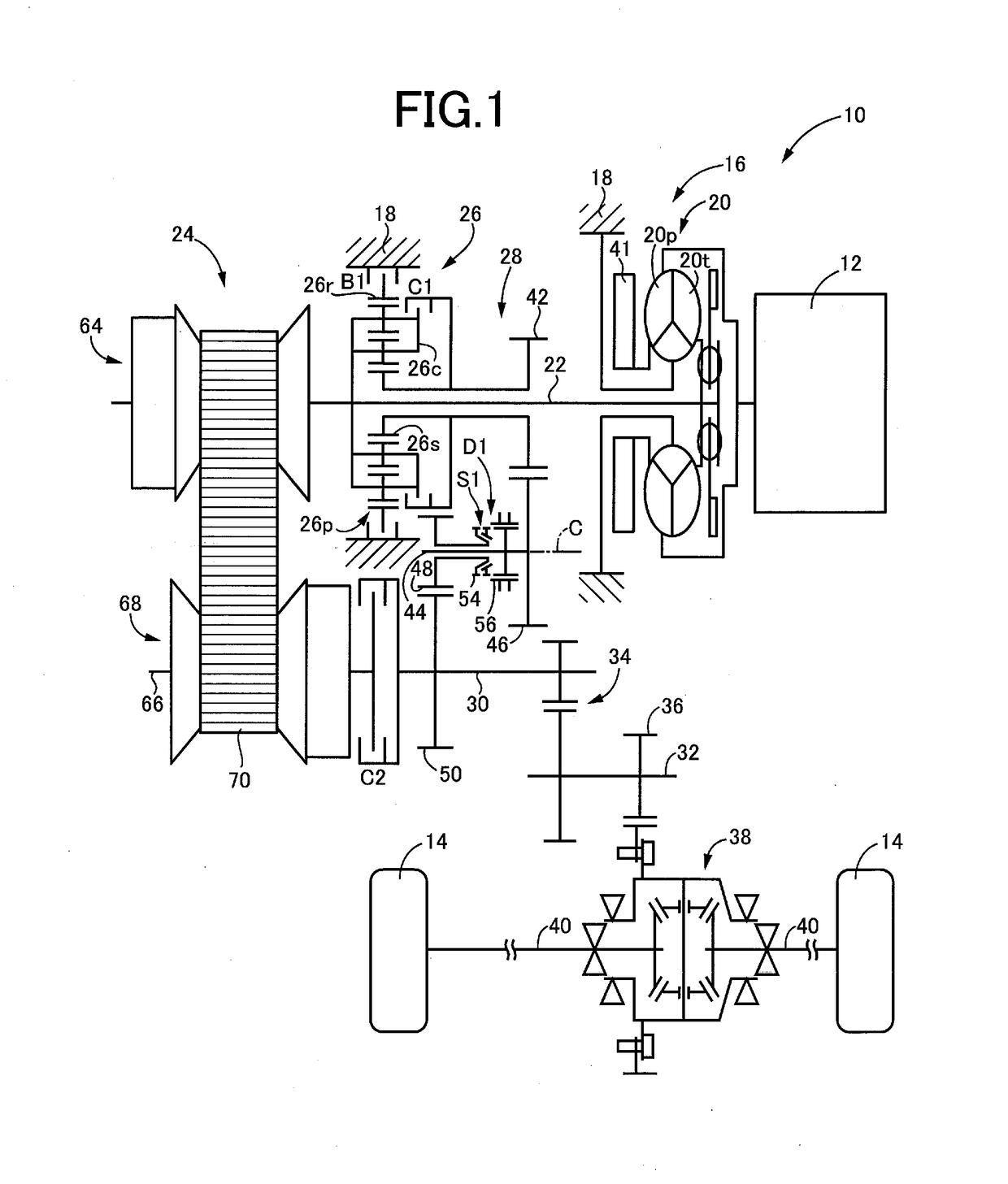
[0040]FIG. 1 is the schematic view showing an arrangement of a vehicle 10 having a power transmitting system 16 according to one embodiment of this invention. As shown in FIG. 1, the vehicle 10 is provided with a vehicle drive power source in the form of an engine 12, drive wheels 14, and the power transmitting system 16 disposed between the engine 12 and the drive wheels 14. The power transmitting system 16 includes, within a stationary member in the form of a housing 18: a fluid-operated power transmitting device in the form of a known torque converter 20 connected to the engine 12; an input shaft 22 connected to the torque converter 20; a continuously variable transmission mechanism in the form of a known belt-and-pulley-type continuously variable transmission 24 (hereinafter referred to as “continuously variable transmission 24”) connected to the input shaft 22; a forward / reverse switching device 26 connected to the input shaft 22; a power transmitting mechanism in the form of a...

second embodiment

[0068]Then, another embodiment of this invention will be described. It is to be understood that the same reference signs as used in the first embodiment will be used to in the following embodiment, to identify the corresponding elements, which will not be described redundantly.

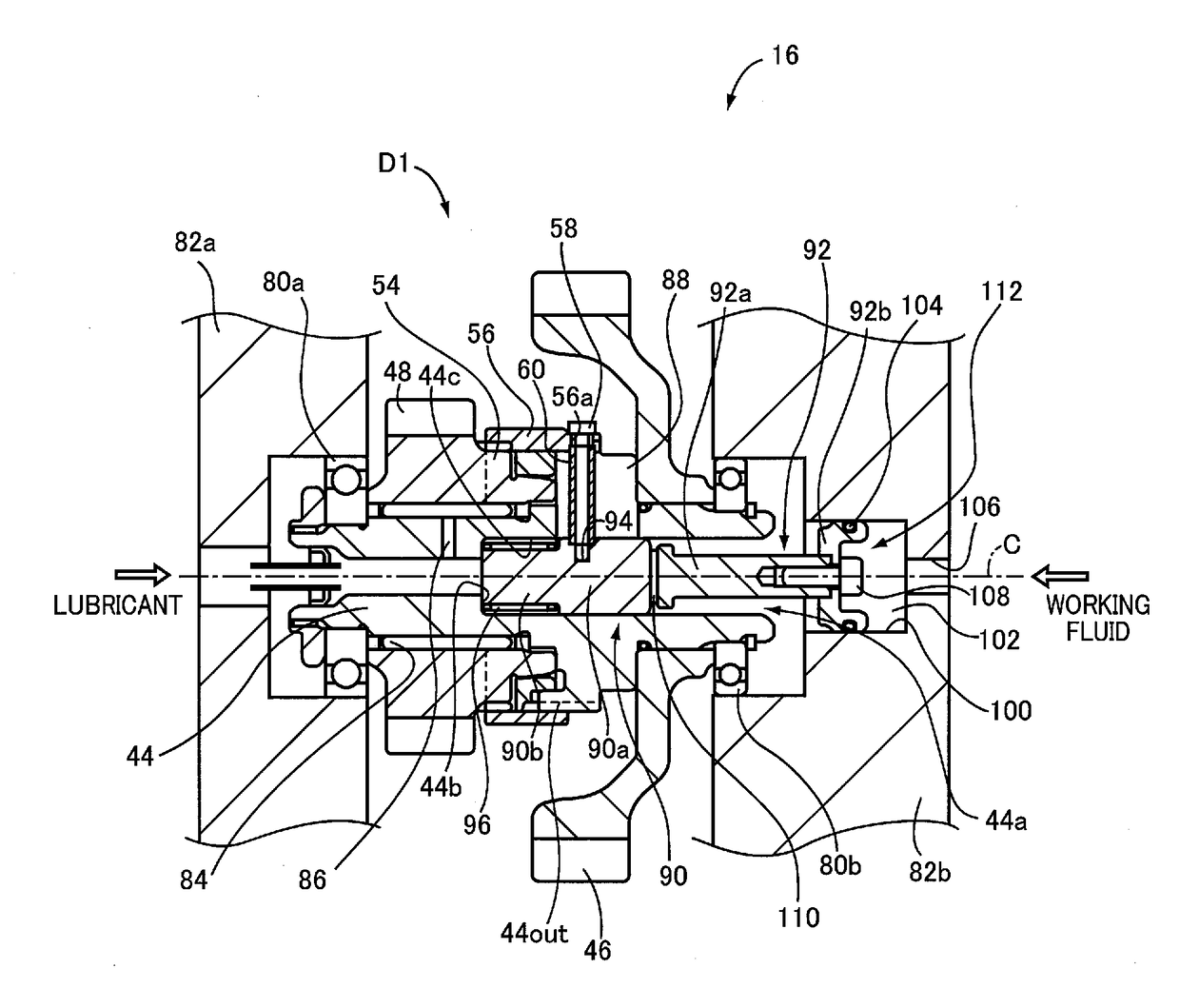
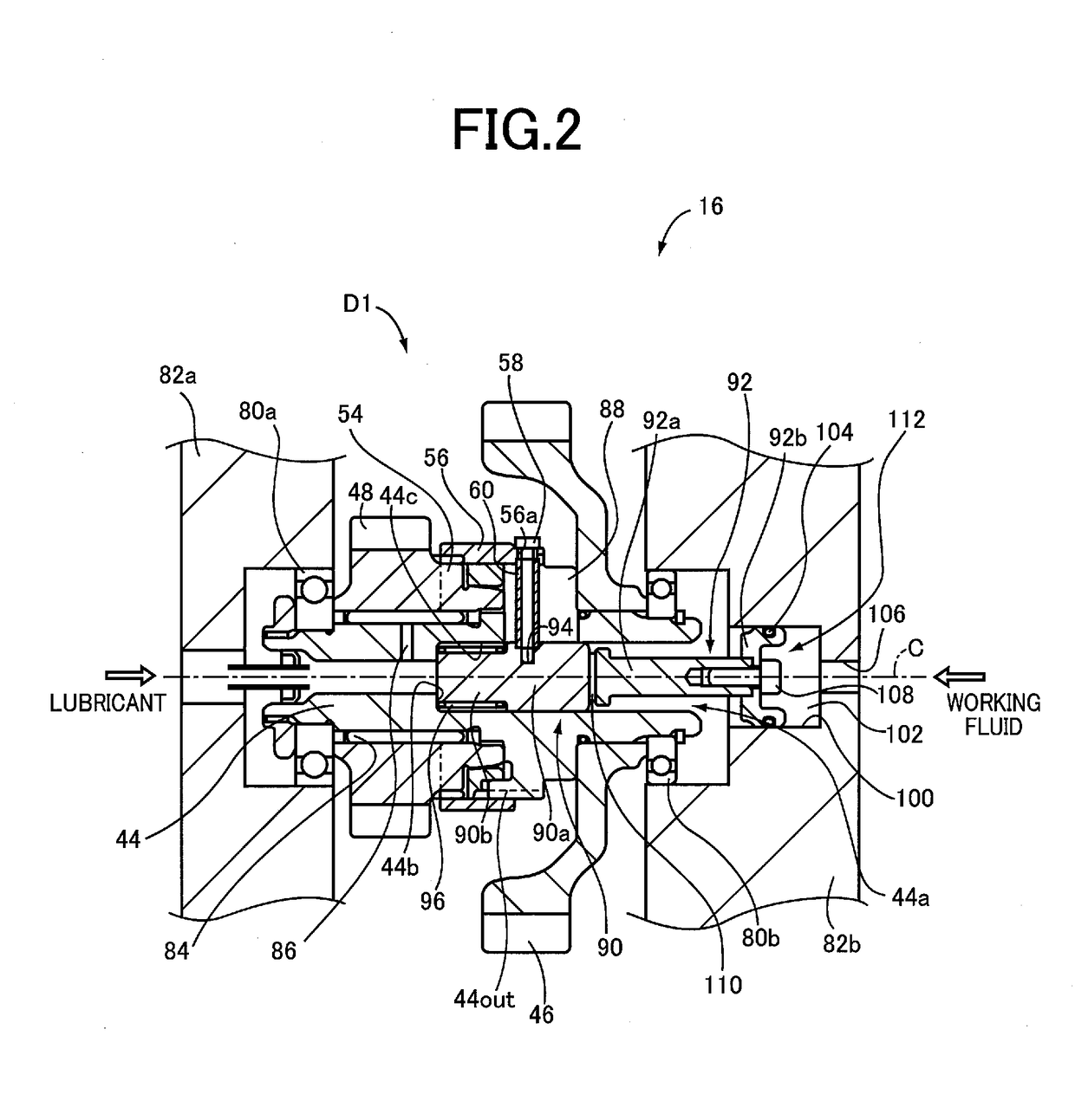
[0069]FIG. 4 is the schematic view showing an arrangement of the vehicular power transmitting system 16 according to another embodiment of this invention, when the dog clutch D1 having the synchro-mesh mechanism is placed in its engaged state. In the present second embodiment, the first piston 90, and an axial end portion of a second piston 200 which is on the side of the first piston 90, are accommodated within the center bore 44a formed in the gear mechanism counter shaft 44, such that the first piston 90 and the second piston 200 are disposed coaxially with the gear mechanism counter shaft 44 having the axis C. The first piston 90 is located in an axial end portion of the center bore 44a, which is on the si...


PUM


Abstract

A power transmitting system including: a first piston disposed within a center bore formed through the rotary shaft such that the first piston is axially reciprocable; a sleeve connected to the first piston and having internal teeth meshing with the external teeth of the rotary shaft so that the sleeve is rotated with the rotary shaft, and such that the sleeve is axially reciprocable together with the first piston according to axial movements of the first piston; a synchronizer ring supported in sliding contact with an outer circumferential tapered surface of the clutch gear such that the synchronizer ring is rotatable relative to the clutch gear; and an actuator including a second piston to axially advance the first piston for thereby bringing the sleeve's internal teeth into meshing engagement with the clutch gear through the synchronizer ring. The first piston and second piston are disposed coaxially with the rotary shaft.

Description

CROSS REFERENCE TO RELATED APPLICATION[0001]The present application claims the priority from Japanese Patent Application No. 2017-034222 filed on Feb. 26, 2017, the disclosure of which is herein incorporated by reference in its entirety.FIELD OF THE INVENTION[0002]The present invention relates in general to a vehicular power transmitting system, more particularly to a vehicular power transmitting system provided with a dog clutch having a synchro-mesh mechanism.BACKGROUND OF THE INVENTION[0003]There is known a vehicular power transmitting system including a dog clutch which has a synchro-mesh mechanism and which is configured to selectively connect and disconnect a rotary shaft having external teeth and rotatable about its axis, and a clutch gear rotatable relative to the rotary shaft, to and from each other. JP-2016-001029A discloses an example of such a vehicular power transmitting system.SUMMARY OF THE INVENTION[0004]The dog clutch having the synchro-mesh mechanism disclosed in J...

Claims


Application Information

Patent Timeline
Patent Type & Authority Applications(United States)
IPC IPC(8): F16D23/06F16H63/30F16D23/02F16D25/08F16D25/12F16H57/04
CPCF16H57/0478F16H2063/3093F16D2023/0631F16D2023/0693F16D2300/06F16D23/06F16H63/3023F16D23/025F16D25/086F16D25/123F16H57/043F16D23/0612F16H37/022B60Y2400/72F16D11/14F16D25/06F16D2300/24F16D2500/10462F16H57/0424F16H57/0471B60K17/02B60K17/10F16D25/08
Inventor YOSHIDA, MICHIONAKADA, HIROFUMISAITO, KAZUNORI
Owner TOYOTA JIDOSHA KK
Why Eureka
Try Eureka