Fuel injector

Inactive Publication Date: 2003-07-24
ROBERT BOSCH GMBH
View PDF4 Cites 7 Cited by
  • Summary
  • Abstract
  • Description
  • Claims
  • Application Information

AI Technical Summary

Benefits of technology

[0010] The fuel injector according to the present invention having the characterizing feature of the main claim has the advantage over the related art that a very sudden increase in the flow-through occurs during the opening operation. Thereby, a larger portion of the total spray-discharged fuel is spray-discharged in a narrowly defined time window.[0011] A gap situated between a valve needle and a valve-seat member ensures a nearly constant flow-through at the beginning of the opening operation. Therefore, the flow-through cross-section at the valve-seat surface increases during the lift movement, without a change in the amount of fuel to be spray-discharged, which is determined by a gap having a constant cross-section.[0012] Due to the very rapid increase in the cross-section, a steep rise in the amount of fuel being spray-discharged by the fuel injector per time unit takes place. The portion of the fuel being spray-discharged via the preliminary jet is small. This makes it possible to better adjust the mixture formation with regard to ignition time and combustion time. The result is a more efficient combustion, resulting in turn in lower consumption and lower exhaust gas values.[0013] Measures described in the dependent claims make advantageous refinements of the fuel injector according to the present invention possible.[0014] One advantage is the large diameter of the valve needle, which, in comparison to the small radial dimension of the valve-closure member, makes the steep rise of the flow-through possible. The small radial dimension of the valve-closure member results in a great surface pressure on the sealing seat, thus ensuring a good sealing function.[0015] A further advantage is the simple and independent adjustment of the steady-state flow-through for the completely opened fuel injector. The adjustment may take place either upstream from the gap or downstream from the gap. Swirl-generating components may also be used. The limitation of the fuel during opening of the fuel injector has no effect on the formation of a swirl.[0016] The reduction of the preliminary jet, having little swirl, is also advantageous. The poor atomization at the beginning of the spray-discharge operation is hereby reduced. The portion of the total amount of spray-discharged fuel, spray-discharged with a good swirl, is hereby increased. This results in a finer droplet distribution and therefore in improved volatilization of the fuel, which ultimately results in improved combustion.[0017] The advantages mentioned above for the opening operation of the fuel injector also apply in an analog manner to the closing operation of the fuel injector. The advantageous effect on harmful emissions of the engine is even greater in this case. The fuel amount supplied toward the end of the combustion cycle, which cannot be combusted optimally, is significantly reduced, thereby resulting in lesser consumption along with improved harmful emissions.

Problems solved by technology

The disadvantage in the described fuel injectors is the slow increase of the fuel amount spray-discharged per unit of time during the opening and closing operations.
The result is a very long period of time of slowly increasing fuel flow-through from the beginning of spray discharge until reaching the steady-state spray-discharge amount with a completely opened fuel injector.
However, this entails a high manufacturing complexity.

Method used


Image

  • Fuel injector
  • Fuel injector
  • Fuel injector

Examples


Embodiment Construction

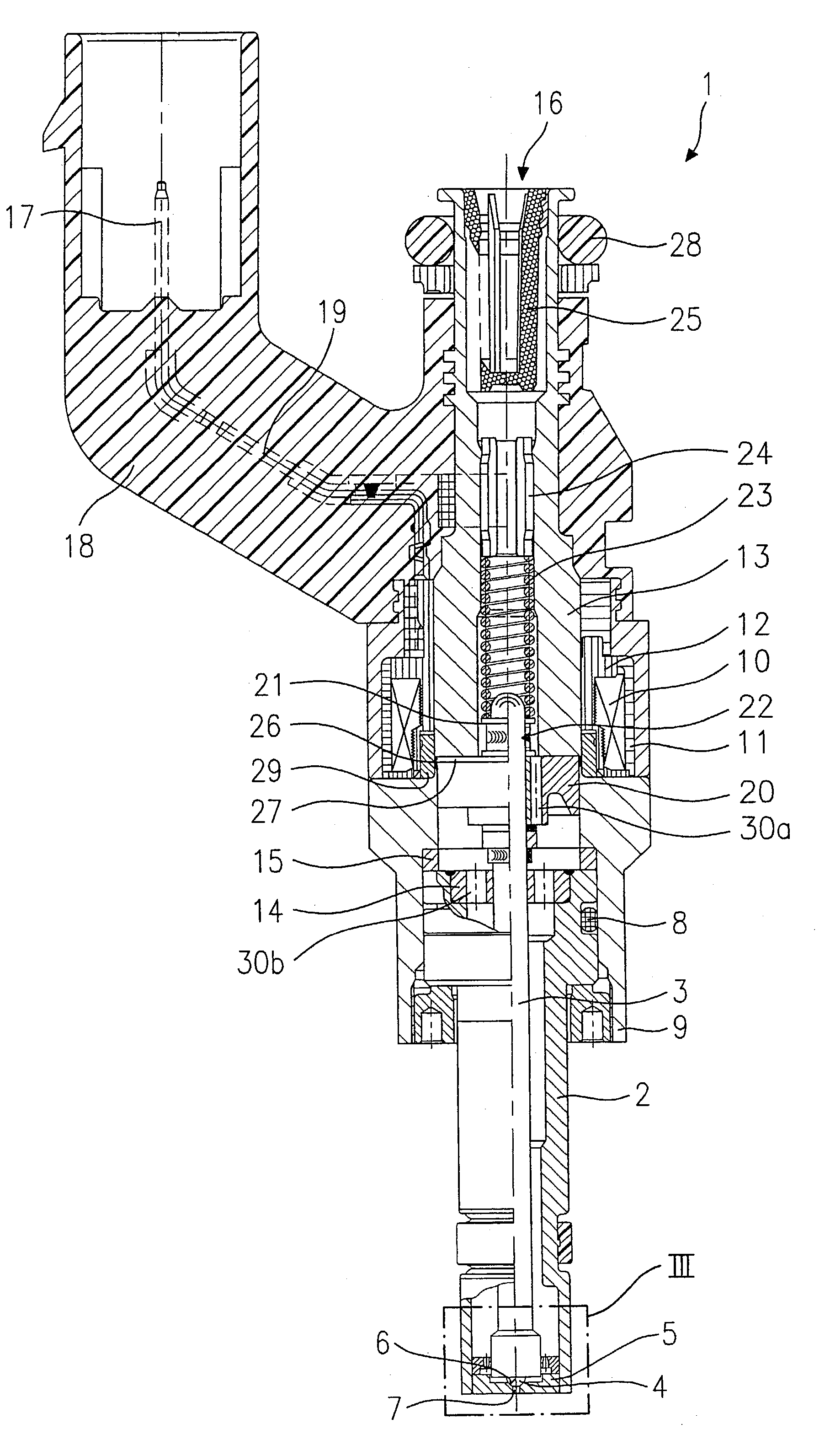
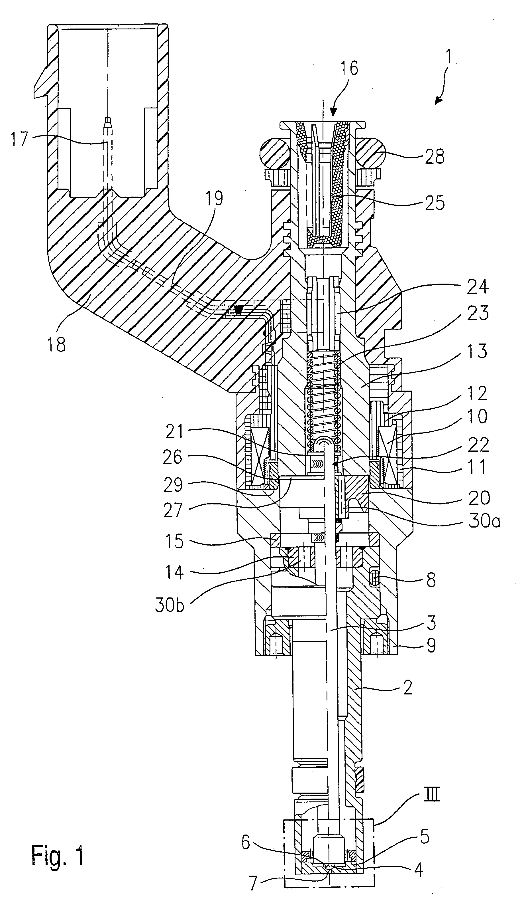
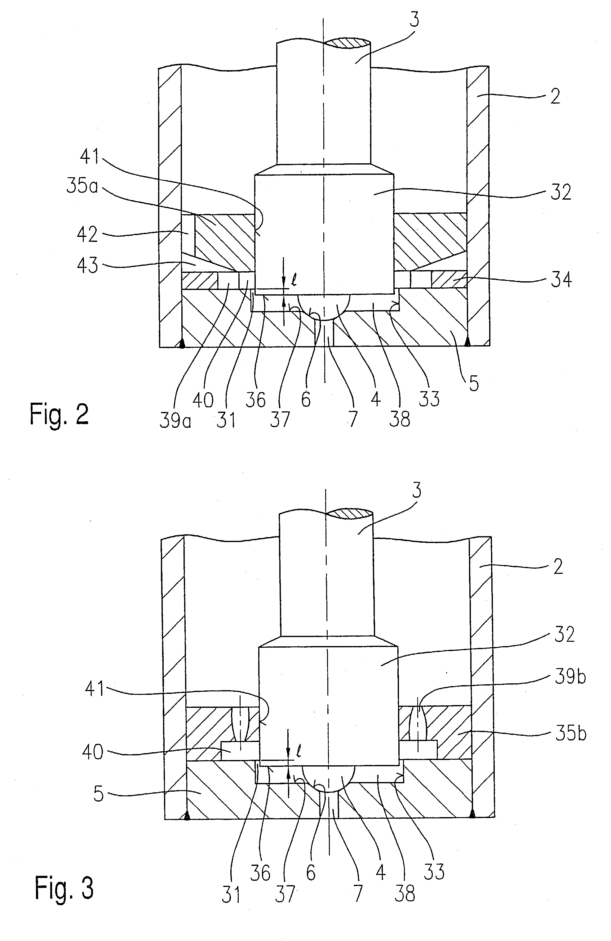
[0024] Before describing exemplary embodiments of a fuel injector 1 according to the present invention in greater detail on the basis of FIGS. 2 through 4, fuel injector 1 according to the present invention is briefly explained in an overall description with regard to its essential components, on the basis of FIG. 1, for better understanding of the present,invention.

[0025] Fuel injector 1 is configured in the form of a fuel injector 1 for fuel injection systems of mixture-compressing, spark-ignited internal combustion engines. Fuel injector 1 is particularly suitable for direct injection of fuel into a combustion chamber (not shown) of an internal combustion engine.

[0026] Fuel injector 1 includes a nozzle body 2 in which valve needle 3 is situated. Valve needle 3 is mechanically linked to a valve-closure member 4, which cooperates with a valve-seat surface 6, situated on a valve-seat member 5 to form a sealing seat. Fuel injector 1 in the exemplary embodiment is an electromagnetical...


PUM


Abstract

A fuel injector for fuel injection systems of internal combustion engines includes a valve-seat member (5), in which a valve-seat surface (6) is introduced, which cooperates with a valve-closure member (4), mechanically linked to a valve needle (3), to form a sealing seat, and at least one spray-discharge orifice (7); in the idle state of the fuel injector (1) a gap (31), whose length (1) is smaller than the opening lift of the fuel injector (1), is situated between a downstream part of valve needle (3) and a recess (33) introduced in valve-seat member (5) on its upstream side.

Description

BACKGROUND INFORMATION[0001] The present invention is based on a fuel injector according to the preamble of the main claim.[0002] Fuel injectors, which are opened by using a valve-closure member which lifts up inwardly from a valve-seat surface, are known. German Patent Application 197 36 682 A1 describes a fuel injector where the valve-closure member and the valve needle are designed in one piece. The conically tapering downstream end of the valve-closure member is pressed in its idle state by a spring force onto a valve-seat surface, which is joined downstream by a spray-discharge orifice. The spray-discharge orifice and the valve-seat surface are situated in a valve-seat member which is introduced into and welded to a nozzle body from the downstream side.[0003] A swirl disk having recesses with a tangential component for generating a swirl in the fuel flow is situated in the fuel injector upstream from the valve-seat surface; on its way to the sealing seat, the fuel flows through...

Claims


Application Information

Patent Timeline
IPC IPC(8): F02M51/06F02M51/08F02M61/16F02M61/18
CPCF02M51/0614F02M51/0671F02M61/1806F02M61/18F02M61/162
Inventor DANTES, GUENTERNOWAK, DETLEF
Owner ROBERT BOSCH GMBH
Why Eureka
Try Eureka