Spiral perfusion dilatation balloon for use in valvuloplasty procedure

a technology of dilatation balloon and valvuloplasty, which is applied in the field of spiral perfusion balloon for use in valvuloplasty procedure, can solve the problems of restricting blood flow and interfering with the proper functioning of the valv

Active Publication Date: 2012-09-27
MEDTRONIC VASCULAR INC
View PDF2 Cites 54 Cited by
  • Summary
  • Abstract
  • Description
  • Claims
  • Application Information

AI Technical Summary

Benefits of technology

[0005]Embodiments hereof relate to a spiral perfusion dilatation balloon for use in a valvuloplasty procedure. The spiral perfusion balloon includes an inflatable tube having an inflation lumen extending therethrough. The tube is wound about a central axis to create a series of flanking coils having inner surfaces that define a perfusion lumen of the perfusion balloon to allow blood flow therethrough. When inflated, the coiled tube forms an hourglass profile having an intermediate section disposed between proximal and distal sections. At least one winding of the intermediate section has a reduced outer diameter relative to an outer diameter of at least one winding in each of the proximal and distal sections. When deflated, the coiled tube is collapsed to a low profile.
[0006]According to another embodiment hereof, a balloon catheter for use in a valvuloplasty procedure includes a catheter shaft having an inflation lumen. A spiral perfusion dilatation balloon is mounted about a distal portion of the catheter. The spiral perfusion balloon is formed from an inflatable tube having a balloon inflation lumen extending therethrough and being in fluid communication with the catheter inflation

Problems solved by technology

Heart valves, such as the mitral valve, tricuspid, aortic and pulmonic valves, are sometimes damaged by disease or by aging, which can interfere with the proper functioning of the valve.
Heart valve problems generally take one of two forms: stenosis

Method used


Image

  • Spiral perfusion dilatation balloon for use in valvuloplasty procedure
  • Spiral perfusion dilatation balloon for use in valvuloplasty procedure
  • Spiral perfusion dilatation balloon for use in valvuloplasty procedure

Examples


Embodiment Construction

[0022]Specific embodiments of the present invention are now described with reference to the figures, wherein like reference numbers indicate identical or functionally similar elements. The terms “distal” and “proximal” are used in the following description with respect to a position or direction relative to the treating clinician. “Distal” or “distally” are a position distant from or in a direction away from the clinician. “Proximal” and “proximally” are a position near or in a direction toward the clinician.

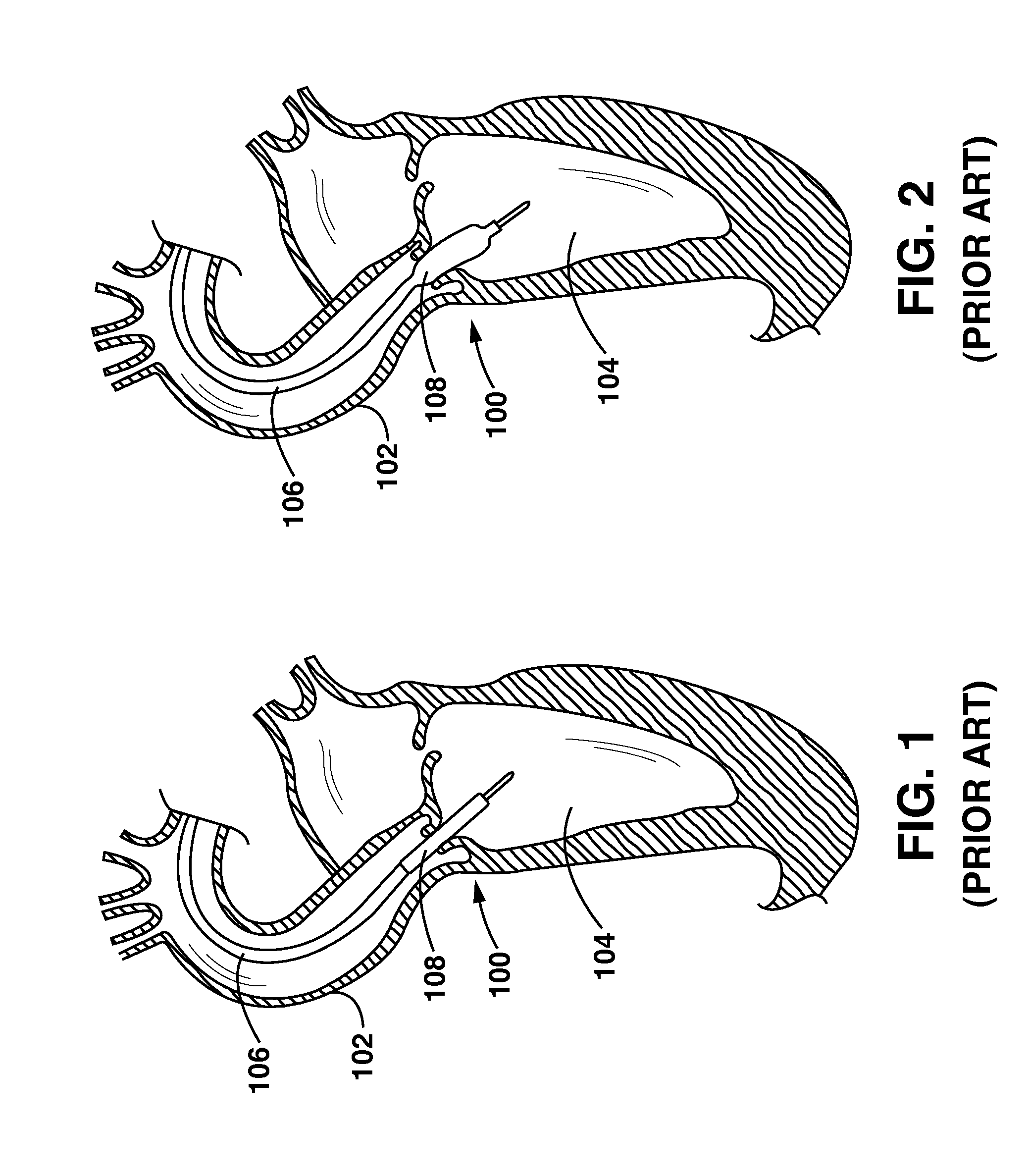
[0023]The following detailed description is merely exemplary in nature and is not intended to limit the invention or the application and uses of the invention. Although the description of the invention is in the context of treatment of heart valves, such as the mitral, tricuspid, aortic and pulmonic valves, the invention may also be used in any other body passageways where it is deemed useful. Furthermore, there is no intention to be bound by any expressed or implied theory pres...


PUM


Abstract

A balloon dilatation catheter for use in a valvuloplasty procedure includes a catheter shaft and a spiral perfusion balloon mounted thereon. The perfusion balloon is formed from an inflatable tube that is in fluid communication with a catheter shaft inflation lumen. The inflatable tube is coiled into a series of windings that in an inflated configuration form a cylindrical or hourglass profile. In the inflated configuration, inner surfaces of the coiled windings of the inflatable tube define a perfusion lumen to allow blood flow through the perfusion balloon. Adjacent windings may be secured together with a flexible adhesive and/or a support weave formed from one or more filaments of material that criss-crosses between the adjacent windings along substantially the entire length of the spiral perfusion balloon.

Description

FIELD OF THE INVENTION[0001]The invention relates to a spiral perfusion balloon for use in a valvuloplasty procedure.BACKGROUND OF THE INVENTION[0002]Heart valves, such as the mitral valve, tricuspid, aortic and pulmonic valves, are sometimes damaged by disease or by aging, which can interfere with the proper functioning of the valve. Heart valve problems generally take one of two forms: stenosis, in which a valve does not open completely such that the opening is too small, resulting in restricted blood flow; or insufficiency, in which a valve does not close completely, permitting blood to leak backward across a valve that should be closed. The most common form of heart valve disease is aortic stenosis where the aortic valve leaflets become calcified and stiff, reducing the functioning valve area. The underlying disease state may be congenital or acquired. Valve replacement may be required in severe cases to restore cardiac function. The native aortic valve is removed and replaced w...

Claims


Application Information

Patent Timeline
IPC IPC(8): A61M25/10A61F2/958
CPCA61M25/1002A61M25/1029A61M2025/1097A61M2025/1084A61M25/104A61B2017/00783
Inventor KELLY, JOHNKELLY, BRIANRABARIMANANTSOA-JAMOUS, HERINAINA
Owner MEDTRONIC VASCULAR INC
Why Eureka
Try Eureka