Welding electrode stickout monitoring and control

a technology of welding electrodes and stickouts, applied in the field of welding, can solve problems such as increased spatter, unwanted effects, and deformation of welds, and achieve the effects of reducing the life of contact tips, reducing welding efficiency, and increasing spatter

Inactive Publication Date: 2012-10-04
ILLINOIS TOOL WORKS INC
View PDF9 Cites 101 Cited by
  • Summary
  • Abstract
  • Description
  • Claims
  • Application Information

AI Technical Summary

Benefits of technology

[0006]There is a need, therefore, for improved techniques for measuring or estimating stickout, and for using the measured or estimated stickout for monitoring and/or control of the welding wire or welding operation.
[0007]The present invention provides welding systems designed to respond to such needs. In accordance with an exemplary implementation, a welding system comprises a sensor configured to sense a wel

Problems solved by technology

A continuing issue in MIG and related welding processes is variability in the extension of the welding electrode from the structure supporting it in the welding torch.
At the same time, incorrect stickout can lead to degrada

Method used


Image

  • Welding electrode stickout monitoring and control
  • Welding electrode stickout monitoring and control
  • Welding electrode stickout monitoring and control

Examples


Embodiment Construction

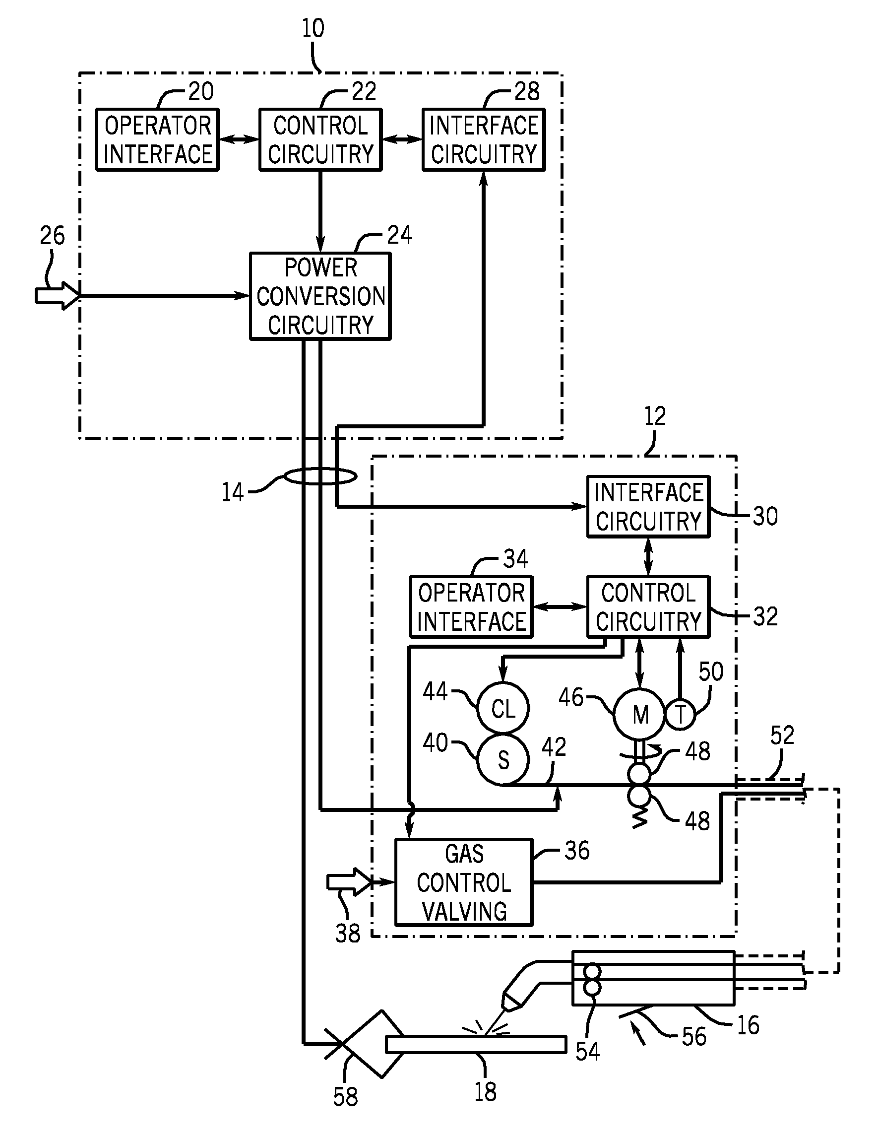
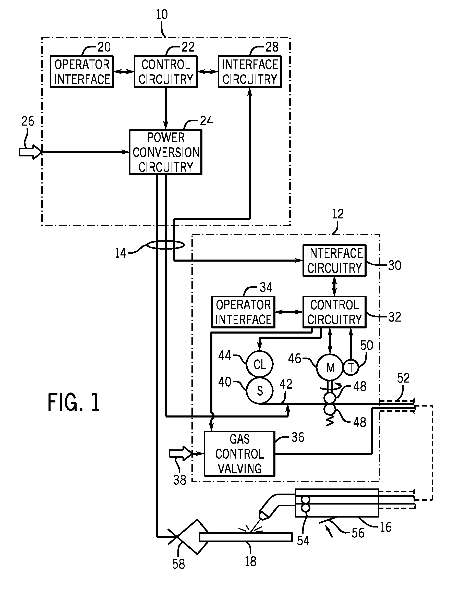
[0016]Turning now to the drawings, and referring first to FIG. 1, an exemplary welding system is illustrated as including a power supply 10 and a wire feeder 12 coupled to one another via conductors or conduits 14. In the illustrated embodiment the power supply 10 is separate from the wire feeder 12, such that the wire feeder may be positioned at some distance from the power supply near a welding location. However, it should be understood that the wire feeder, in some implementations, may be integral with the power supply. In such cases, the conduits 14 would be internal to the system. In embodiments in which the wire feeder is separate from the power supply, terminals are typically provided on the power supply and on the wire feeder to allow the conductors or conduits to be coupled to the systems so as to allow for power and gas to be provided to the wire feeder from the power supply, and to allow data to be exchanged between the two devices.

[0017]The system is designed to provide ...


PUM

PropertyMeasurementUnit
Timeaaaaaaaaaa
Sizeaaaaaaaaaa
Currentaaaaaaaaaa

Abstract

Stickout of a welding electrode wire from a welding torch is determined during welding, and based upon a welding parameter, such as welding current. Different relationships are used for the determination depending upon whether the welding wire is in a short-circuit condition or an arc condition. The stickout may be converted to a standardized unit of measure to make it readily understandable to an operator. The stickout may be logged and associated with other parameters and information, such as workpiece, operator, welding system, date and time. The stickout may be used as the basis for an alarm or a disabling operation. Moreover, the stickout may be provided on a readout for the operator. It may also be used as a basis for controlling a wire feeding apparatus that retracts the welding wire to a desired stickout following a weld.

Description

CROSS REFERENCE TO RELATED APPLICATIONS[0001]This application claims the benefit of U.S. Provisional Patent Application No. 61 / 468,826, entitled “Stickout Calculator”, filed on Mar. 29, 2011, and of U.S. Provisional Patent Application No. 61 / 557,808, entitled “Welding Electrode Stickout Monitoring and Control”, filed on Nov. 9, 2011, both of which are herein incorporated by reference in their entireties.BACKGROUND[0002]The invention relates generally to welders, and more particularly to a welder configured to perform a welding operation in which a welding wire is advanced from a welding torch.[0003]A wide range of welding systems and welding control regimes have been implemented for various purposes. In continuous welding operations, metal inert gas (MIG) techniques allow for formation of a continuing weld bead by feeding welding wire shielded by inert gas from a welding torch. Electrical power is applied to the welding wire and a circuit is completed through the workpiece to sustai...

Claims


Application Information

Patent Timeline
IPC IPC(8): B23K9/10
CPCB23K9/0956B23K9/0953B23K9/173
Inventor HUTCHISON, RICHARD MARTINUECKER, JAMES LEEHOLVERSON, TODD EARLFROLAND, KNUT NORMANO'DELL, MICHAEL J.PULS, KENNETH J.DAVIDSON, ROBERT R.SCHUH, RICHARD
Owner ILLINOIS TOOL WORKS INC
Why Eureka
Try Eureka