RF impedance detection using two point voltage sampling

a technology of impedance detection and voltage sampling, applied in the direction of impedence networks, multiple-port networks, electrical apparatus, etc., can solve the problems of shift in antenna center frequency, impedance mismatch, and stretched performance limits of embedded antenna technology

Active Publication Date: 2012-10-04
TEXAS INSTR INC
View PDF0 Cites 15 Cited by
  • Summary
  • Abstract
  • Description
  • Claims
  • Application Information

AI Technical Summary

Problems solved by technology

As a result, the performance limits of embedded antenna technology are being stretched.
In addition, the body effects of a head or hand near the antenna contribute to capacitive loading which also results in an impedance mismatch.
This can lead to a shift in antenna center frequency and an increased VSWR mismatch.
In addition to reception problems, any mismatch will further result in a reduction in power radiated from the antenna.
A phase detector having good accuracy and low current is difficult to achieve over the 690 Mhz to 2690 Mhz range of interest in many cell phone applications.

Method used


Image

  • RF impedance detection using two point voltage sampling
  • RF impedance detection using two point voltage sampling
  • RF impedance detection using two point voltage sampling

Examples


Embodiment Construction

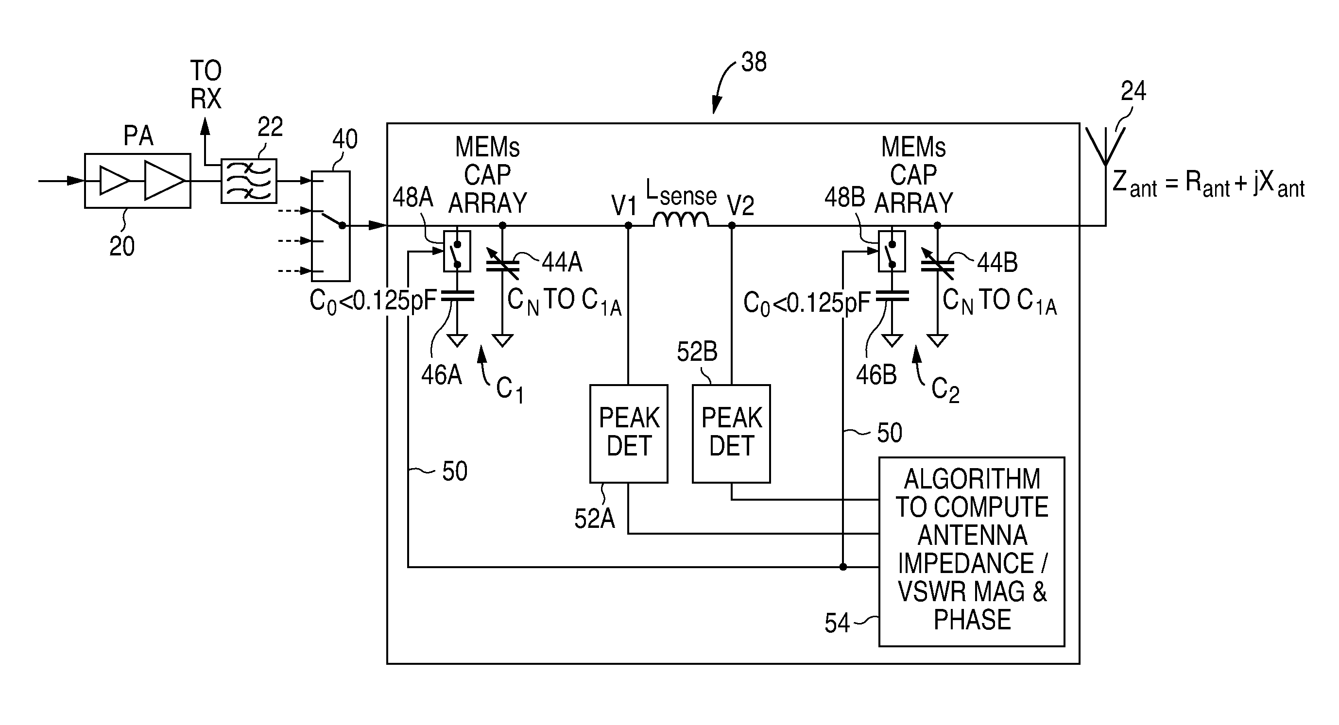
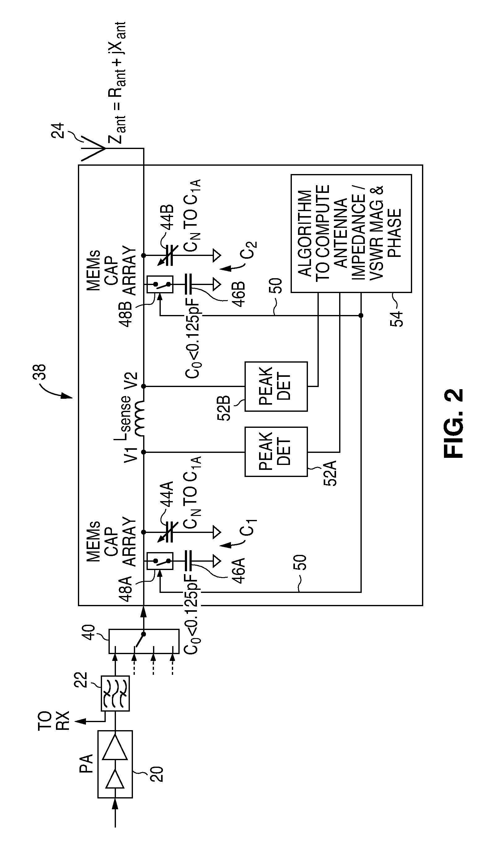
[0014]Referring again to the drawings, FIG. 2 shows an adaptive RF matching network module 38 in accordance with one embodiment of the present invention. An RF power amplifier 20 is coupled to a first port of the network module 38 by way of a duplexer 22 followed by an RF switch 40 which switches between various transceiver paths to accommodate various mobile communication standards such as GSM, WCDMA, LTE, etc. Another port of the network module 38 is for connecting to an antenna 24. Antenna 24 functions to radiate the RF energy from the amplifier 20 and to receive RF signals which are provided to receiver circuitry by way of the duplexer 22. In many applications such as cellular phones, antenna 24 is a narrow bandwidth miniaturized antenna having a high Q. As a result, the antenna is subject to detuning due to fluctuating body effects and changes in the handset form factor. This detuning has an adverse effect on transmitted radiated power efficiency and over the air receiver sensi...


PUM


Abstract

An adaptive impedance matching module having an adjustable impedance matching network with an input for receiving an RF power source and an output to be connected to an antenna, and first and second voltage measurement device configured to sense a voltage at respective first and second nodes on the impedance matching network. A network adjuster circuit is provided to switch the impedance matching network between a first state where first and second voltages are sensed on the respective first and second nodes and a second state where third and fourth voltages are sensed on the respective first and second nodes. Processing circuitry is provided which determines the matched load impedance based upon the first, second, third and fourth sensed voltages and including matching adjustment circuitry configured to adjust the matching impedance in the event the matched load impedance differs from a target load impedance by more that a predetermined amount.

Description

BACKGROUND OF THE INVENTION[0001]1. Field of the Invention[0002]The present invention relates generally to RF impedance measurement and in particular to RF impedance measurements using two point voltage sampling without a phase detector. Some embodiments also relate to adjusting an impedance matching network after the measurement.[0003]2. Description of Related Art[0004]Mobile handsets such as cellular phones are being manufactured using higher levels of integration and use in broader frequency band coverage. As a result, the performance limits of embedded antenna technology are being stretched. Variations in load impedance at the antenna due to environmental changes such as the position at which the phone is held, the frequency band being used and other contributors create a mismatch or increased voltage standing wave ratio (VSWR) at the antenna port. In addition, the body effects of a head or hand near the antenna contribute to capacitive loading which also results in an impedance...

Claims


Application Information

Patent Timeline
Patent Type & Authority Applications(United States)
IPC IPC(8): H03H7/40
CPCH03H7/40
Inventor KEESE, WILLIAM O.RADOVANOVIC, SASASIMON, DANIEL L.
Owner TEXAS INSTR INC
Why Eureka
Try Eureka