Display device and display method therefor

a technology of a display device and a display method, applied in the field of display devices, can solve problems such as extremely dark red, and achieve the effects of reducing tone values, high luminance, and maintaining color balan

Inactive Publication Date: 2012-10-04
SHARP KK
View PDF4 Cites 19 Cited by
  • Summary
  • Abstract
  • Description
  • Claims
  • Application Information

AI Technical Summary

Benefits of technology

[0028]According to the first aspect of the present invention, when a tone value exceeding a predetermined limit is to be provided to any subpixel of a specific color included in the display panel, the luminance adjustment portion decreases tone values to be provided to all subpixels of the specific color to a predetermined limit or less, and correspondingly decreases tone values to be provided to all subpixels of the other colors, so that color balance can be maintained between the specific color and the other colors, and the lighting control portion controls the luminance of the light sources to increase, thereby compensating for a display luminance reduction of the subpixels, so that a high luminance can be achieved.
[0029]According to the second aspect of the present invention, when the maximum calculated by the maximum value calculation portion for the tone values to be provided to the subpixels of the specific color included within one frame period is greater than or equal to a predetermined limit, the luminance adjustment portion decreases the tone values, and the lighting control portion increases the luminances of the light sources in accordance with the maximum value, so that a high luminance can be achieved while maintaining color balance for all pixels.
[0030]According to the third aspect of the present invention, the specific-color correction portion multiplies the tone values to be provided to the subpixels of the specific color by a predetermined correction gain, thereby generating corrected tone values, so that the specific color can be appropriately corrected even if it is dark (due to, for example, a small pixel area), and the luminance decrease adjustment portio

Problems solved by technology

However, in the case of the liquid crystal display device with the pixel configuration as shown in FIG. 8, for example, when a line of the primary color red is

Method used


Image

  • Display device and display method therefor
  • Display device and display method therefor
  • Display device and display method therefor

Examples


Embodiment Construction

[0048]Hereinafter, an embodiment of the present invention will be described with reference to the accompanying drawings.

1. Overall Configuration

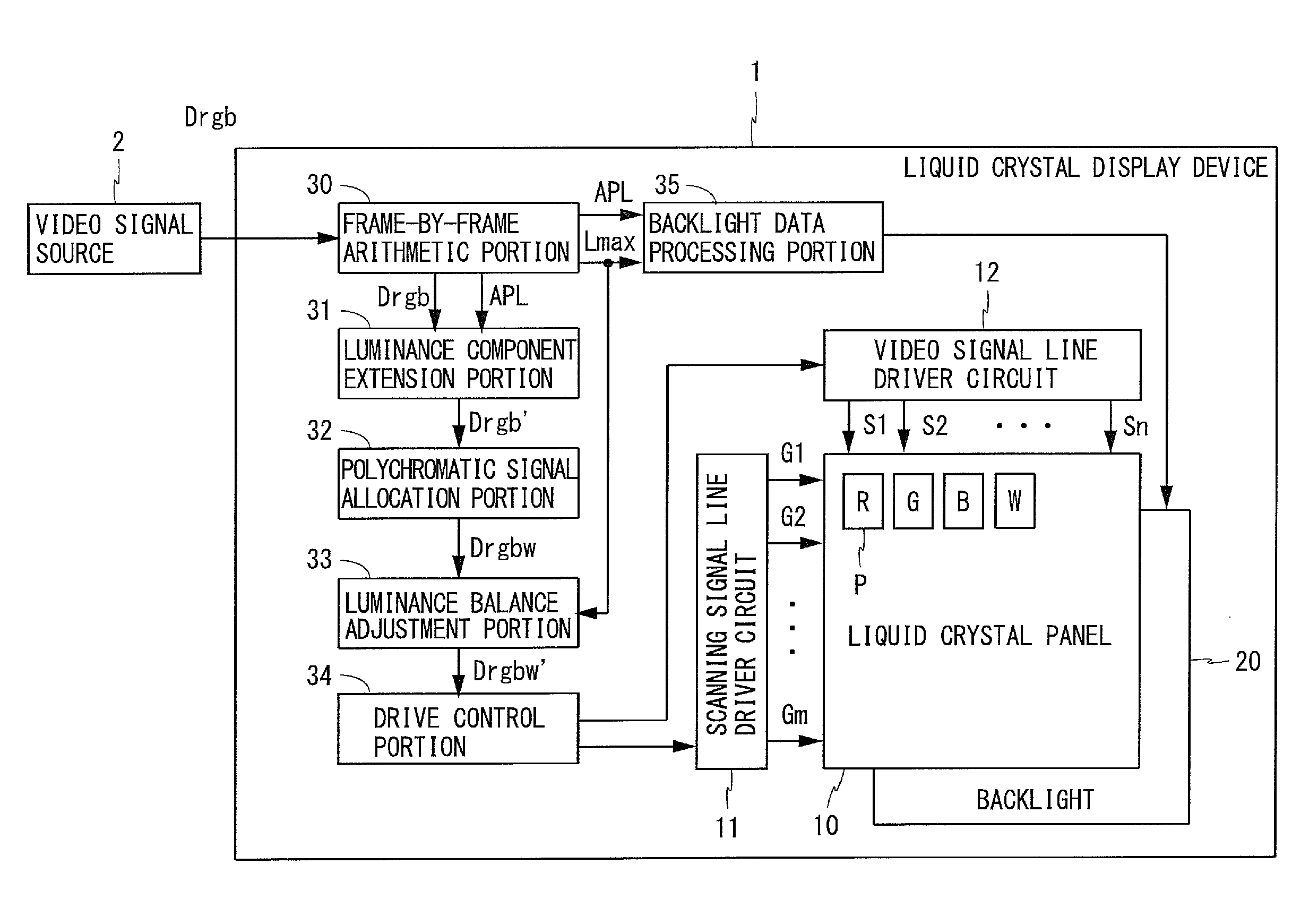
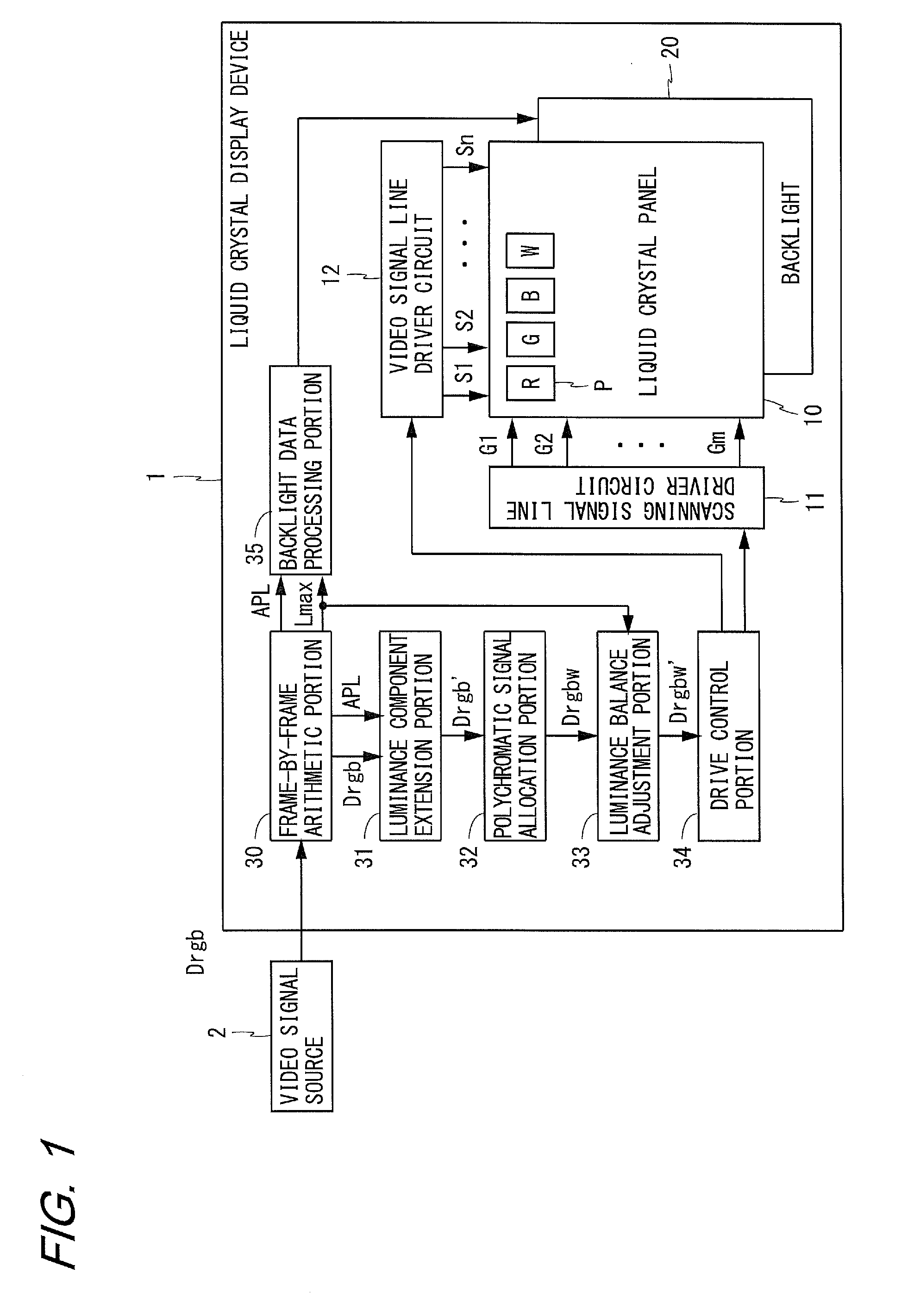
[0049]FIG. 1 is a block diagram illustrating the configuration of a liquid crystal display device according to an embodiment of the present invention. The liquid crystal display device 1 shown in FIG. 1 includes a liquid crystal panel 10, a scanning signal line driver circuit 11, a video signal line driver circuit 12, a backlight 20, a frame-by-frame arithmetic portion 30, a luminance component extension portion 31, a polychromatic signal allocation portion 32, a luminance balance adjustment portion 33, a drive control portion 34, and a backlight data processing portion 35. In the following, “m” is an integer of 2 or more, and “n” is a multiple of 4.

[0050]The liquid crystal panel 10 includes m scanning signal lines G1 to Gm, n video signal lines S1 to Sn, and (m×n) pixel circuits P. The scanning signal lines G1 to Gm, are arranged in paralle...


PUM


Abstract

In the present display device with each pixel being composed of subpixels of four or more colors, a backlight data processing portion sets a backlight source luminance to be high enough to compensate for a display luminance reduction caused by a maximum luminance adjustment portion (332) multiplying input pixel data for G by an adjustment gain, such that the value of the input pixel data for G does not exceed the maximum pixel value, after a G correction portion (331) corrects the input pixel data for G to compensate for a display luminance reduction due to the area of (subpixel) G being half of others. Thus, it is possible to realize high color reproducibility and a high luminance as realized by conventional liquid crystal display devices with a three-color, RGB, pixel configuration.

Description

TECHNICAL FIELD[0001]The present invention relates to display devices, more specifically to a display device including a display panel with each pixel being composed of subpixels of four or more colors.BACKGROUND ART[0002]Conventionally, liquid crystal display devices use color filters of three colors, red, green, and blue (RGB), to provide color image display. In such a liquid crystal display device, each pixel is composed of pixels representing three colors, red, green, and blue (each being referred to as a “subpixel”), as shown in FIG. 7. By adjusting transmittance for each subpixel, a desired color is displayed in each pixel. Recent years have seen increasing demand for such liquid crystal display devices to have a wider range of color reproduction (enhanced color reproducibility). Moreover, liquid crystal display devices, such as portable electronic devices, are increasingly used outdoors, and to ensure satisfactory visibility in the environment with intense outside light, ther...

Claims


Application Information

Patent Timeline
IPC IPC(8): G09G5/10
CPCG02F1/133514G02F2201/52G09G3/3426G09G2320/0646G09G2320/0242G09G2320/0271G09G3/3648
Inventor KATAGAMI, MASAYUKIBAN, ATSUSHITSUBATA, TOSHIHIDEYOSHIDA, TAKEHISA
Owner SHARP KK
Why Eureka
Try Eureka