
Method and device for generating a representation of surroundings

a technology of surroundings and methods, applied in the field of methods and devices for generating a representation of surroundings, can solve problems such as the difficulty of an operator to correctly estimate the distance to objects located on the water surfa

Inactive Publication Date: 2012-10-04
DIEHL BGT DEFENCE GMBH & CO KG
View PDF3 Cites 16 Cited by
  • Summary
  • Abstract
  • Description
  • Claims
  • Application Information

AI Technical Summary

Benefits of technology

[0003]It is accordingly an object of the invention to provide a method and a device for generating a representation of surroundings which overcome the above-mentioned disadvantages of the prior art methods and devices of this general type, which allows the surrounding area to be monitored particularly well.
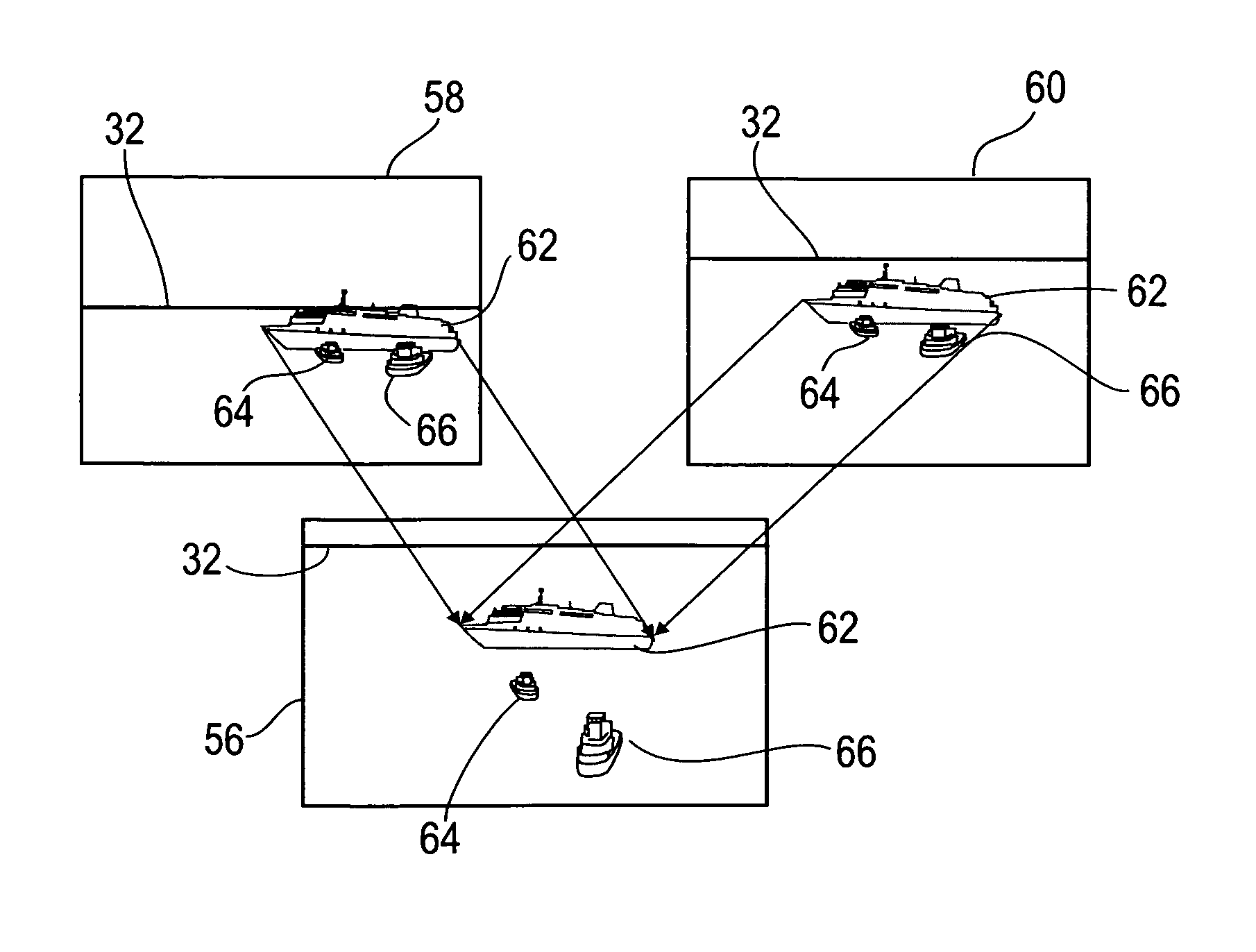
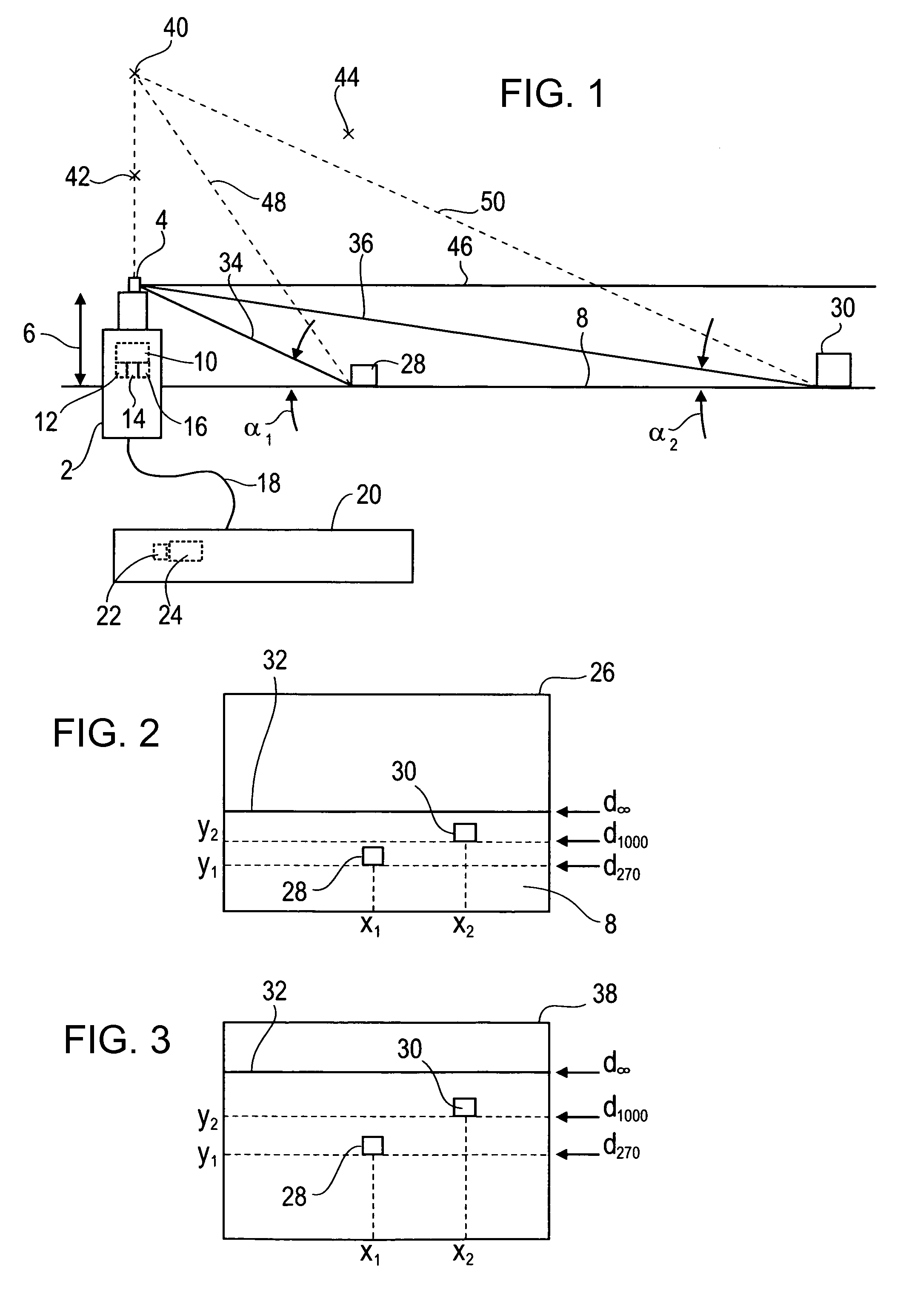
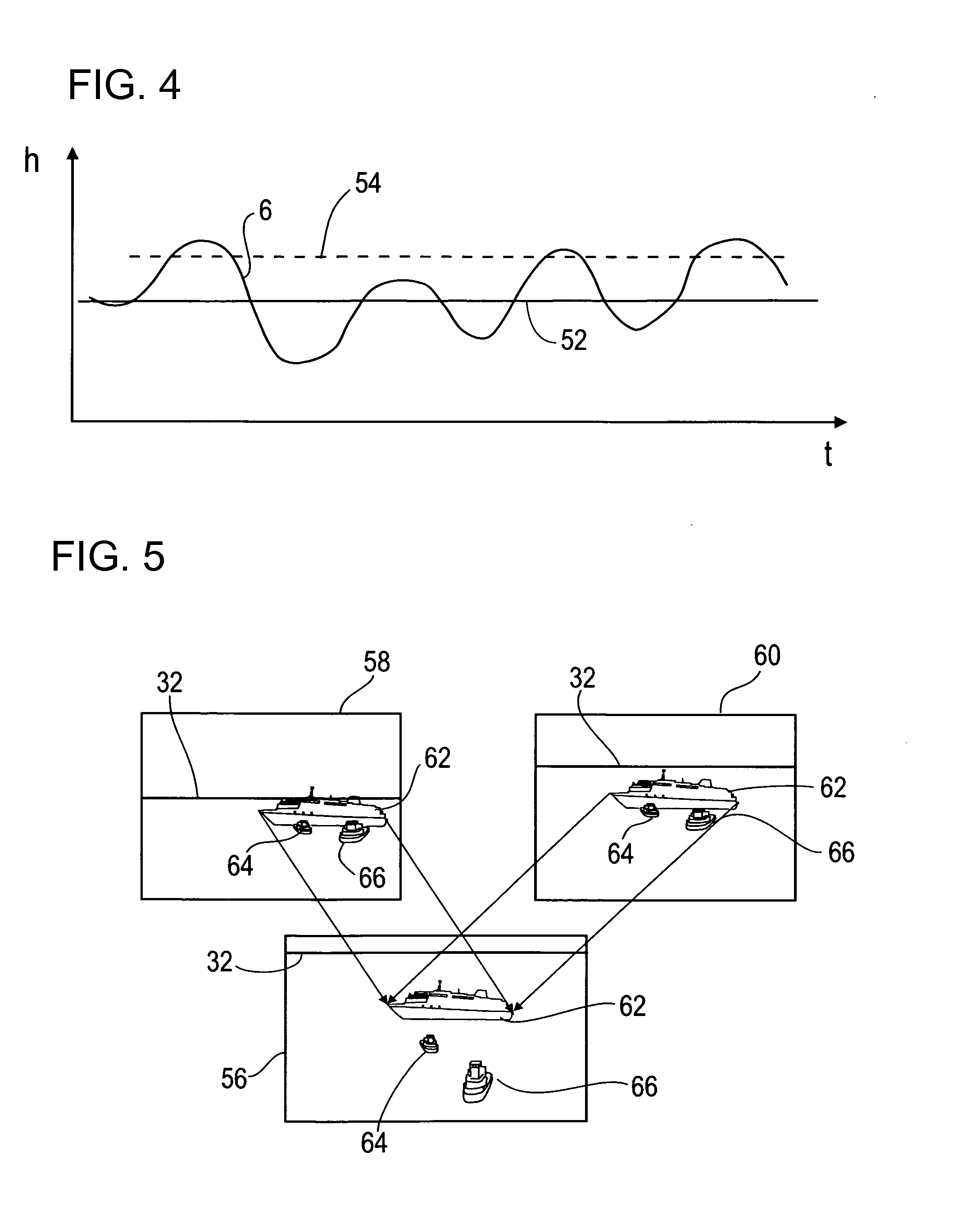
[0006]The choice of a suitable observation point allows the actual surrounding area to be represented virtually in such a way that it is possible to better estimate a distance, for example, between a marine vessel on the water surface and the buoy. For example, if the observation point with respect to the topography is selected to be above the camera position then it is possible to view the objects on the water surface from further above, as a result of which the entire water surface appears over a larger area on the displayed virtual image. The distance can be estimated well by the position of the objects on the surface, which is represented in magnified form by the new perspective.
[0008]In order to produce the virtual representation in a simple form, it is advantageous if voxels which each have three-dimensional spatial information are produced from pixels in the image and the virtual representation is produced from the spatial information in the voxels. The known topography and the camera position, whose position in or above the topography is known, allows a distance from an object imaged at the pixel in the surrounding area to the camera position to be calculated for each pixel. Since the two-dimensional image position of each pixel in the image is known, this two-dimensional information, together with the distance information, allows the spatial information to be associated with each pixel. The three-dimensional position in space of each object which is represented in the pixels is therefore known, all round the camera position.
[0016]In addition, it is advantageous to determine the camera alignment into the surrounding area. This is particularly advantageous when a plurality of images are recorded with a different camera alignment. The camera alignment can be determined with the aid of a sensor, for example an acceleration sensor and / or a compass, for example, with the aid of a known and mean alignment, for example a mean elevation. Determination of the camera alignment relative to the topography allows the image section located in the topography to be determined, and thus makes it possible to detect the position of the pixels, or of objects imaged in these pixels, in the topography.
[0018]A further advantageous embodiment of the invention proposes that when there is a movement of the camera a recording time of the image is selected as a function of the camera position. By way of example, if the camera is moved up and down on a marine vessel or a buoy as a result of the sea state, it is advantageous for the recording time to be selected such that the camera position is as high as possible above a mean position. This makes it possible to achieve a good overview of the surrounding area, and there are few image disturbances caused by imaged wave troughs and wave peaks concealing the horizon, whose real topography is inconsistent with the assumed topography. By way of example, it is possible to select a recording time above a predetermined height above a reference point. The predetermined height may in turn be made dependent on the magnitude of the movement of the camera position within, for example, a predetermined time interval.

Problems solved by technology

A limitation hereto is the fact that the camera position is only slightly above the water surface.
When the surveillance image, that is to say the representation of the actual surrounding area, is shown on a display, then it is difficult for an operator to correctly estimate a distance to objects which are located on the water surface.

Method used


Image

  • Method and device for generating a representation of surroundings
  • Method and device for generating a representation of surroundings
  • Method and device for generating a representation of surroundings

Examples


Embodiment Construction

[0031]Referring now to the figures of the drawing in detail and first, particularly, to FIG. 1 thereof, there is shown a communication and surveillance buoy 2 having a camera 4 which is arranged at a height 6 above a water surface 8 when the sea is calm. For signaling purposes, the camera 4 is connected to a processing device 10, which is arranged in the interior of the surveillance buoy 2 together with a data memory 12, an acceleration sensor 14 and a compass 16. The surveillance buoy 2 is connected via a towing cable 18 to a submarine, which is towing the surveillance buoy 2. Data can be transmitted via the towing cable 18 from the processing device 10 to a further processing device 22 in the submarine 20, which is connected to a display device 24 in the form of a screen. The surveillance buoy 2 forms an apparatus for production of a representation of a surrounding area on the display device 24 in the submarine 20. For this purpose, the recording of a plurality of images with the ...


PUM


Abstract

It is proposed that, on the assumption that the surrounding area forms a known topography, a representation is produced from a form of the topography, the camera position relative to the topography and the image in the form of a virtual representation of the view from an observation point which is at a distance from the camera position. This makes it possible to select an advantageous perspective of objects which are imaged in the image, thus making it possible for an operator to easily identify the position of the objects relative to the camera.

Description

CROSS-REFERENCE TO RELATED APPLICATION[0001]This application claims the priority, under 35 U.S.C. §119, of German application DE 10 2009 054 214.0, filed Nov. 21, 2009; the prior application is herewith incorporated by reference in its entirety.BACKGROUND OF THE INVENTIONField of the Invention[0002]In order to allow a submarine to reconnoiter a surrounding area as far as possible without being detected, it is known for the submarine to remain close below the water surface and operate a radio link, by a communication mast, which passes through the water surface, or surveilles the surrounding area. However, the submarine is relatively easily accessible to enemy surveillance as a result of the position of the submarine, close below the water surface. The risk of ramming by a marine vessel is also not insignificant. In order to solve this problem, it is known for the submarine to deploy a communication buoy, to which the submarine remains connected. A radio link can be maintained, and t...

Claims


Application Information

Patent Timeline
Patent Type & Authority Applications(United States)
IPC IPC(8): H04N5/225H04N13/02
CPCG06T19/00G06T15/20
Inventor GAGEL, FLORIANKUSHAUER, JORG
Owner DIEHL BGT DEFENCE GMBH & CO KG
Learn More