Connector

Inactive Publication Date: 2012-10-04
HIROSE ELECTRIC GROUP
View PDF22 Cites 23 Cited by
  • Summary
  • Abstract
  • Description
  • Claims
  • Application Information

AI Technical Summary

Benefits of technology

[0073]In the seventh aspect of the present invention, the elastic deformation member is disposed between the movable sleeve and the connector main body. Accordingly, it is possible to automatically return the movable sleeve of the second connector to the initial position from the distal end side or the proximal end side in the axial direction with the simple configuration. As a result, it is possible to reduce a size of the second connector and improve the durability

Problems solved by technology

When the movable sleeve is situated at an initial position, the diameter control portion moves close to or contacts with an outer

Method used


Image

  • Connector
  • Connector
  • Connector

Examples


first embodiment

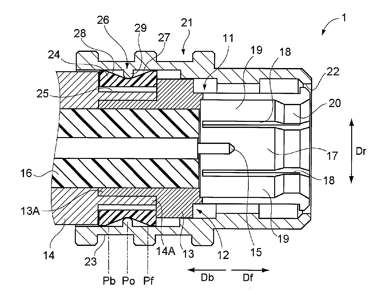
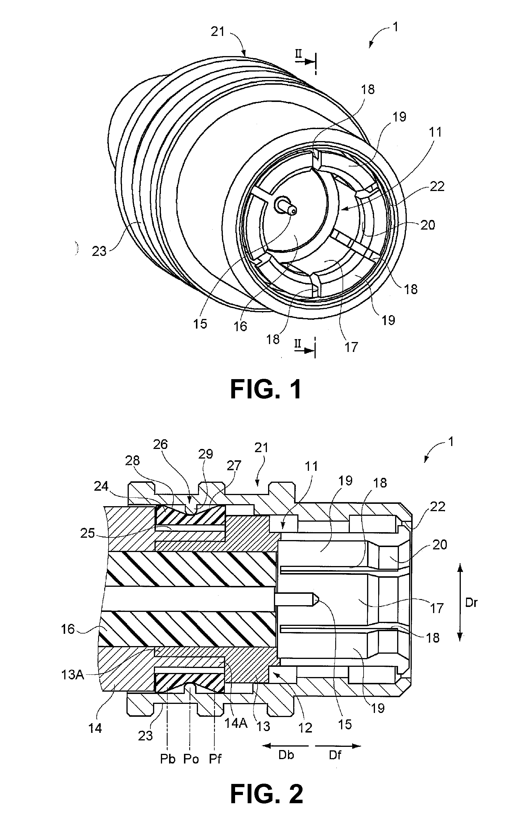
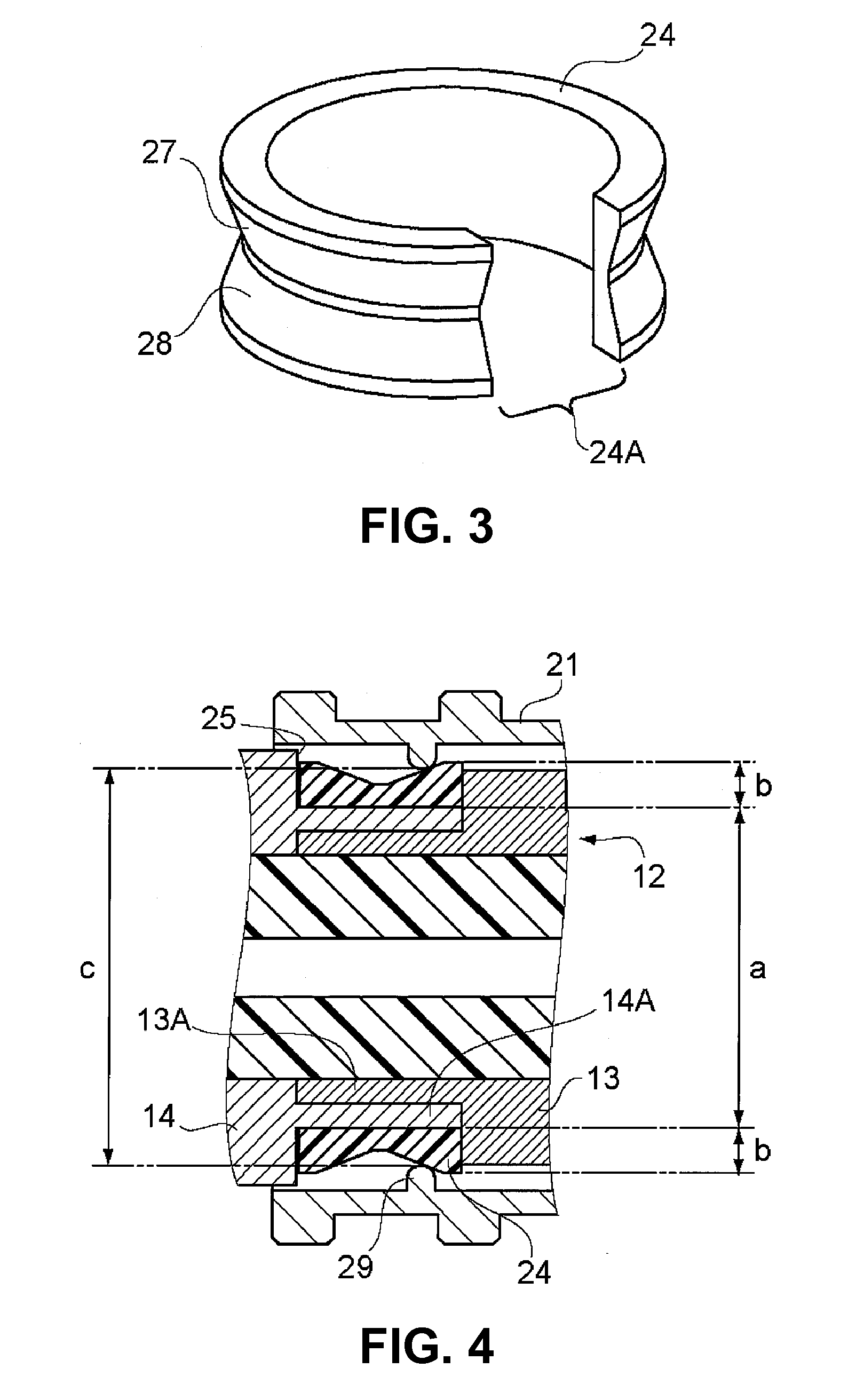
[0091]A first embodiment of the present invention will be explained. FIGS. 1 and 2 show an electrical connector according to a first embodiment of the present invention. FIG. 3 shows an elastic deformation member provided to the electrical connector. FIG. 3 shows measurements of various portions in the electrical connector at a proximal end portion thereof.

[0092]As shown in FIG. 1, the electrical connector 1 according to the first embodiment of the present invention is a coaxial connector equipped with a locking mechanism of push-pull style. The electrical connector 1 is configured substantially with a connector main body 11 and a movable sleeve 21 being movable in a direction of an axis, provided around an outer circumference of the connector main body 11.

[0093]As shown in FIG. 2, the connector main body 11 includes a cylindrical member 12. The cylindrical member 12 forms an outer shell of the connector main body 11. In addition, the cylindrical member 12 functions as an external t...

second embodiment

[0150]A second embodiment of the present invention will be explained next. FIG. 9 is a sectional view showing an electrical connector according to a second embodiment of the present invention. In FIG. 9, components unchanged from the first embodiment have the same numeral references as FIGS. 1 to 8(B) and explanations thereof will be omitted.

[0151]As shown in FIG. 9, the electrical connector 41 according to the second embodiment of the present invention includes an elastic deformation member 42; an accommodating portion 43 and a transmission unit 44 as the mechanism for returning the movable sleeve 21 moved by the operator in the direction of the axis to the initial position automatically. The accommodating portion 43 accommodates the elastic deformation member 42 and the transmission unit 44 generates force bringing back the movable sleeve 21 to the initial position by utilizing elastic force of the elastic deformation member 42.

[0152]The elastic deformation member 42 is made from ...

third embodiment

[0168]A third embodiment of the present invention will be explained next. FIG. 10 is a sectional view showing an electrical connector according to a third embodiment of the present invention. In FIG. 10, components unchanged from the first embodiment have the same numeral references as FIGS. 1 to 8(B) and explanations thereof will be omitted.

[0169]As shown in FIG. 10, the electrical connector 51 according to the third embodiment of the present invention includes an elastic deformation member 52 as a part of the mechanism for returning the movable sleeve 21 moved by the operator in the direction of the axis to the initial position automatically. In the embodiment, the elastic deformation member 52 is made from a metallic material by press working.

[0170]In the embodiment, the elastic deformation member 52 has a C-letter shape as a whole. The elastic deformation member 52 is capable of being deformed with elasticity thereof in the direction of the diameter thereof. The elastic deformat...


PUM


Abstract

A connector to be connected to a mating connector, includes a connector main body including a cylindrical member, a supporting member disposed in the cylindrical member, a terminal supported on the supporting member, and a fitting portion having an engaging portion; a movable sleeve including a diameter control portion; an elastic deformation member disposed to be elastically deformable in a radial direction thereof; an accommodating portion disposed between the connector main body and the movable sleeve for accommodating the elastic deformation member; and a transmission unit for transmitting a force in the axial direction from the movable sleeve to the elastic deformation member when the movable sleeve moves, and for transmitting a force in the radial direction from the elastic deformation member to the movable sleeve when the elastic deformation member returns to an original shape.

Description

BACKGROUND OF THE INVENTION AND RELATED ART STATEMENT[0001]The present invention relates to a connector. More specifically, the present invention relates to a connector such as an electrical connector for connecting devices electrically, in which a locking mechanism is provided for preventing the connector from coming off.[0002]In a conventional connector such as an electrical connector, an optical connector, and so on, a locking mechanism is provided therein for preventing the connector connected to a mating connector from coming off the mating connector. For example, a connector having a circular cross-sectional shape such as a coaxial connector, a multi core connector, and so on, is equipped with the various locking mechanisms such as a screw-in style mechanism, a bayonet style mechanism, a push-pull style mechanism, and so on.[0003]In the conventional connectors described above, the locking mechanism of the push-pull style includes a sleeve having a cylindrical shape on an outer...

Claims


Application Information

Patent Timeline
IPC IPC(8): H01R11/09
CPCH01R13/6277H01R24/40H01R13/639
Inventor MAKI, KENTARO
Owner HIROSE ELECTRIC GROUP
Why Eureka
Try Eureka