Device for positioning and adjusting a viewing axis

a technology of viewing axis and device, which is applied in the field of improving the device for positioning the viewing axis, can solve the problems of complex infrastructure, inability to guarantee optimal accuracy, and high cost, and achieves the effects of simple execution, convenient use, and improved accuracy

Inactive Publication Date: 2012-10-04
CHIRMAT
View PDF0 Cites 29 Cited by
  • Summary
  • Abstract
  • Description
  • Claims
  • Application Information

AI Technical Summary

Benefits of technology

[0021]The invention is also based on the observation that the orientation of the axis of the distal hole changes little even when the nail becomes deformed. The changes of orientation due notably to the nail's curvature are limited and do not prevent the drilling nor the insertion of a screw or a pin taking into account the existing play. It is thus not necessary to provide an adjustment of the inclination of the viewing device's axis; such an adjustment option is even detrimental since it makes the adjustment more complex and slower.
[0022]It is thus possible to make a support that enables a precise adjustment of the viewing device and of the drill according to the most relevant degree or degrees of freedom and to block the translational or rotational movements according to all the other degrees of freedom. In a preferred embodiment, the viewing device and the drill can thus move only by translational and / or rotational movements in a plane perpendicular to the longitudinal axis of the hole in the undeformed nail; the support prevents all other displacements relative to the nail. One thus capitalizes on the a priori knowledge of the theoretical position and orientation of the hole.
[0023]In a first embodiment, the precise adjustments are made according to a single degree of freedom, by a translational movement of the viewing device in a plane perpendicular to the viewing and drilling axis, and along a translational direction perpendicular to the axis of the undeformed nail. This embodiment has the advantage of a very simple execution, since the device requires only a precise adjustment means along a single axis, which is moreover linear. This variant is thus both economical and easy to use.
[0024]In a second embodiment, the adjustments are made by a rotational movement in the plane described here above and around an axis parallel to the viewing and drilling axis. This variant is also economical and easy to use; it furthermore has the advantage of adapting to greater deformations of the nail.
[0025]A degree of precise adjustment by a translational movement of the viewing device parallel to the nail's axis can be provided. This variant increases the cost of the device and makes the adjustment more complex, but provides maximum flexibility and enables the viewing device and the nail's hole to be aligned accurately even in the case of a considerable flexion or deformation of the nail.
[0026]The device thus enables the viewing device to be aligned with the axis of the nail's distal hole only by displacements along one or even two degrees of freedom in a single plane. These displacements are particularly intuitive for the orthopedic surgeon and their effect on the position of the pointer in the viewing device is much easier to predict that in the case of displacements along other degrees of freedom in three dimensions. This results in a shorter adjustment time and length of the operation.

Problems solved by technology

The main difficulty for the surgeons in determining the position and the axis of the distal fixation hole arises from the uncertainty associated with the deformation to which the nail is subjected when it is introduced into the bone, since the nail obviously has elastic properties in order for it to be able to follow the trajectory of the bone's cavity.
Traditionally, the position of the nail is determined by exposition to x-rays, which however requires a complex infrastructure which is not available everywhere.
These electronic apparatus require the presence of a source of current that is not always available.
They furthermore often prove very expensive.
These methods using essentially mechanical viewing apparatus do not however guarantee optimum accuracy, notably as regards the alignment of the drilling axis relative to the hole.
The magnet does indeed allow the hole's position to be localized accurately, but as its field lines are omnidirectional and isotropic, they do not indicate the direction of the hole's axis.
These devices will indeed make it possible to avoid an oblique drilling, but are not of any help when the hole is not at the expected location in the plane.
It is difficult to position a removable magnet correctly inside a deformed nail.
Such a rotational adjustment furthermore does not allow the viewing axis to be adapted in a satisfactory manner when the intramedullary nail is curved according to the shape of the patient's bone, notably when this deformation occurs in a plane perpendicular to the axis of the fixation hole.
The manufacturing costs of such a compass prove high; this device is furthermore difficult to sterilize for repeated use.
This results in a considerable adjustment time, which unnecessarily increases the duration of the operation and complicates rehabilitation.
Other devices on the other hand have adjustment possibilities that are too limited and do not allow a precise adjustment of the orientation or of the position.
This frequently results in the necessity for the orthopedic surgeon to make a hole in the bone that is not perfectly aligned with the hole through the nail.
The screw or pin is then difficult to insert and the surgeon must make an incision unnecessarily large and difficult to heal to allow this screw or pin to be inserted.

Method used


Image

  • Device for positioning and adjusting a viewing axis
  • Device for positioning and adjusting a viewing axis
  • Device for positioning and adjusting a viewing axis

Examples


first embodiment

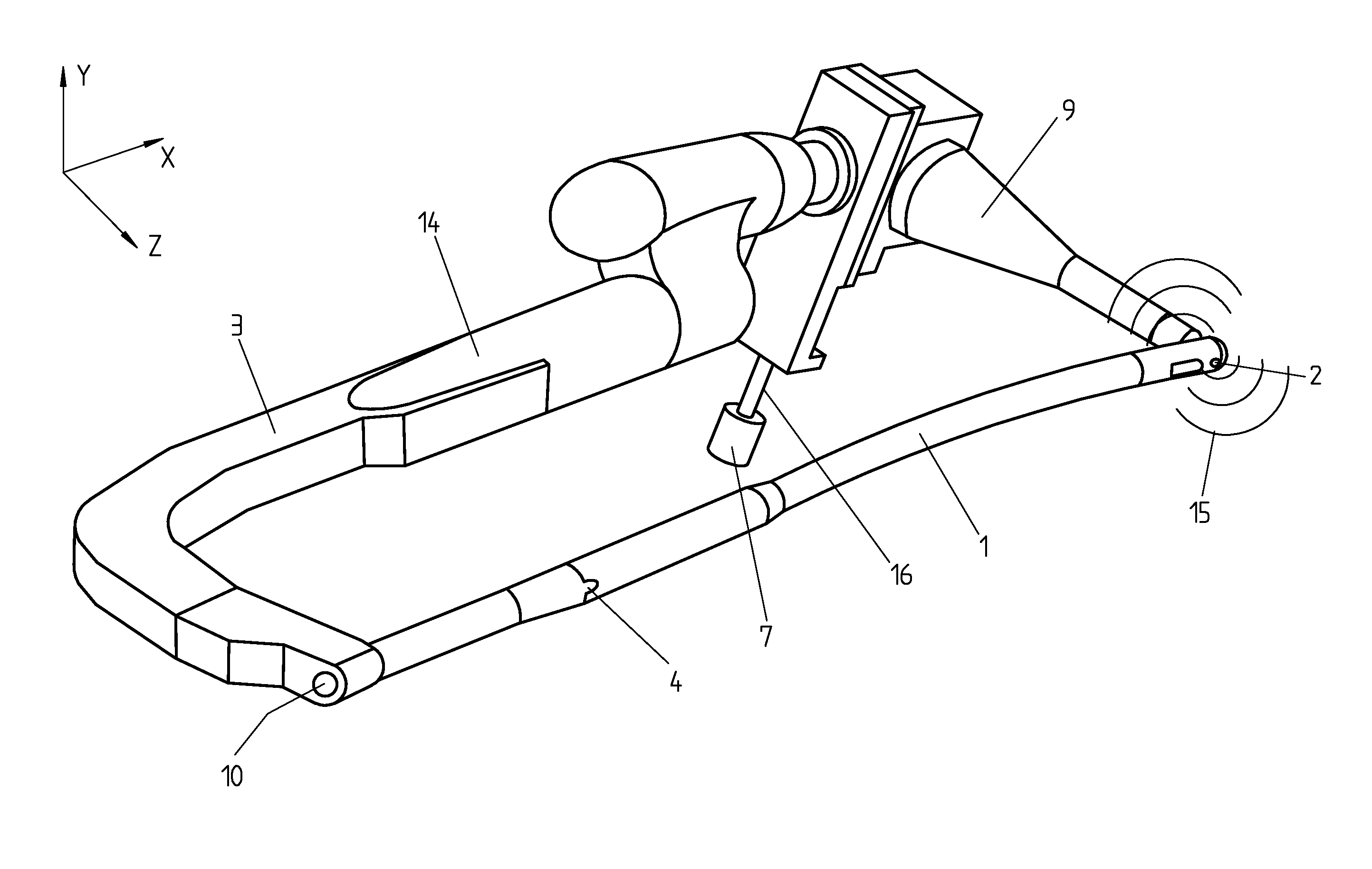
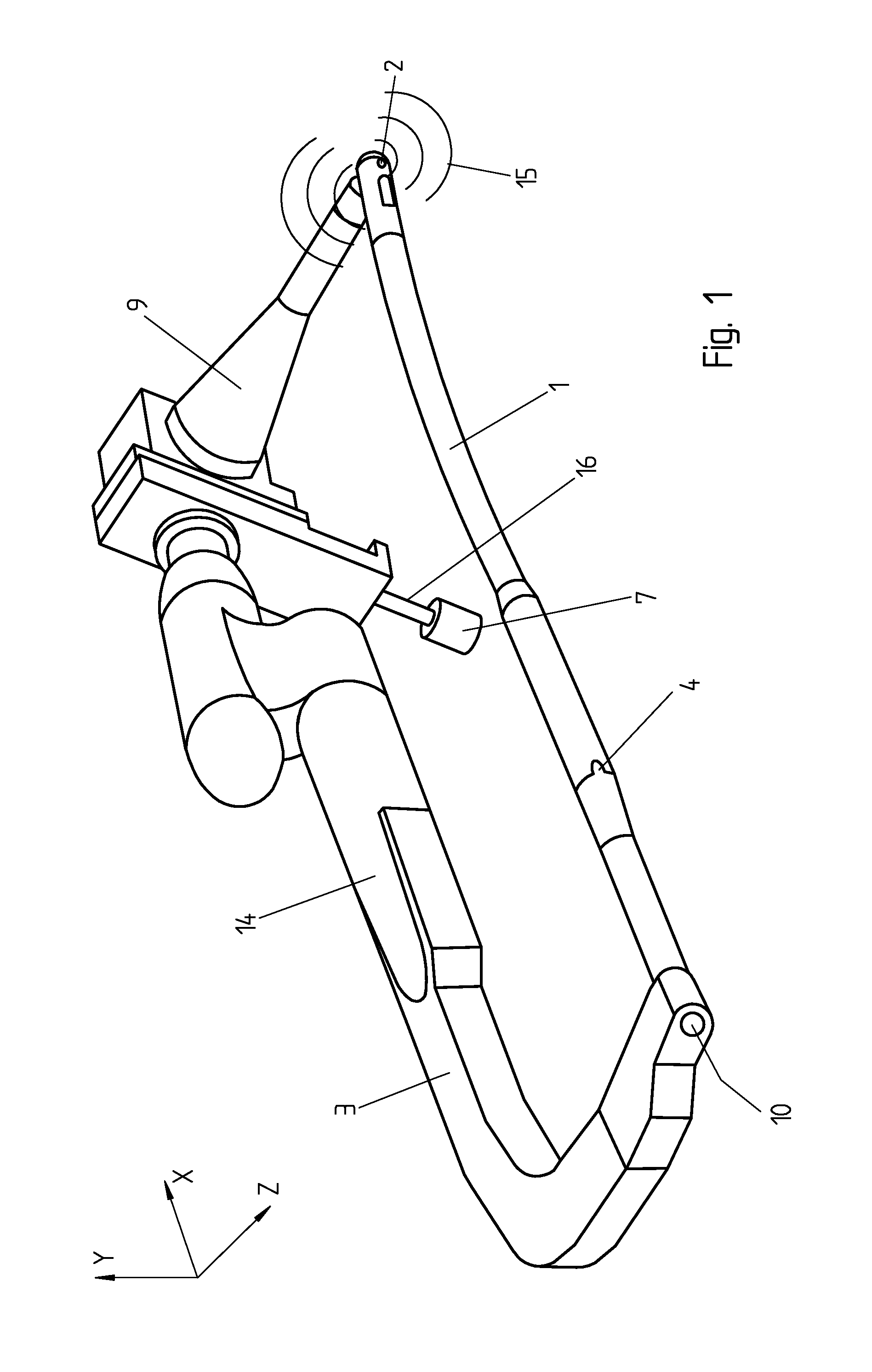
[0039]FIG. 1 is a perspective view of a viewing device according to the invention. The axis X corresponds to the longitudinal axis of the undeformed nail 1 and the axis Z (viewing axis) corresponds to the axis of the viewing device 9 and of the undeformed distal fixation hole 2 (the hole). The rigid support 3 makes it possible to position the viewing device 9 relative to the nail. The reference number 4 indicates a shape-keyed connection 4 where the support 3 is fastened onto the nail 1.

[0040]A removable sleeve 14 allows the length of the rigid support 3 to be adapted depending on the length of nail used; this is not a precise or fine adjustment but only a possibility of adapting to nails of different standard lengths, typically by increments of several centimeters. In one embodiment, the length of the rigid support can be modified by selecting an assembly part, such as the sleeve 14 of FIG. 1, depending on the length of the nail 1.

[0041]The viewing device 9 can be moved closer to o...

second embodiment

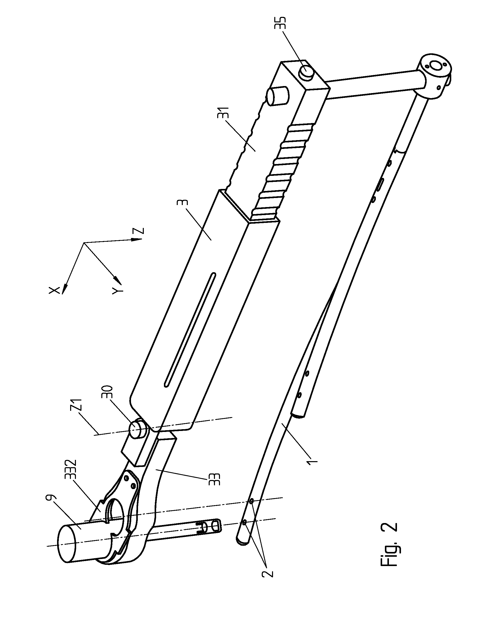
[0050]FIG. 2 illustrates in perspective a device according to the invention wherein the adjustment of the position of the viewing device 9 is made essentially by a rotational movement around an axis Z1 parallel to the viewing and drilling axis / . The device comprises a rigid support 3, for example of carbon fiber, telescopic with an extension portion 31 that makes it possible to coarsely adapt the length of the support along the axis X depending on the length of the nail 1; the adjustment is done advantageously in successive increments, for example in increments spaced by 20 mm or adapted to the available range of length of nails. A scale on the inner tube 31 can be displayed in a window, not represented, in the outer tube 3 in order to indicate the length currently selected. Holding is advantageously achieved by elastic deformation (clipsing) of the increments of the telescopic portion. In another variant illustrated on the FIG. 3, the indexing of the extension length of the telesco...


PUM


Abstract

Method for positioning a viewing axis in relation to a distal fixation hole (2) for an intramedullary nail (1). A rigid support (3) is fixed to the proximal end of the nail (1). An adjustable viewing device (9) is mounted on the rigid support (3). A coarse adjustment is done of the length of the rigid support according to the length of the nail (1). A coarse adjustment is done in order to move the viewing device (9) closer to the nail, taking account of the patient's build. A precise adjustment is done of the position of the viewing device in relation to the nail, involving the translational and/or rotational movement of the viewing device in a plane perpendicular to the longitudinal axis of the viewing device (Z).

Description

RELATED APPLICATIONS[0001]This application is a continuation of international application PCT / EP2009 / 064234 filed on Oct. 28, 2009, the contents of which is hereby incorporated by reference.TECHNICAL FIELD[0002]The present invention concerns an improvement to devices for positioning a viewing axis, notably for localizing a distal hole in an intramedullary nail for the surgical treatment of fractures of long bones.STATE OF THE ART[0003]Centromedullary nails are used in the field of surgery for stabilizing fractures of long bones. This type of nail is inserted in long bones, for example the femur, having central cavities in which they can be lodged by simply drilling the longitudinal extremities of the bone.[0004]When a surgeon wishes to introduce an intramedullary nail into a long bone, for example a femur, he first pierces a longitudinal extremity thereof, generally at the level of the buttocks, and then drives the nail into the bone's central cavity. In order to prevent torsional m...

Claims


Application Information

Patent Timeline
Patent Type & Authority Applications(United States)
IPC IPC(8): A61B17/17
CPCA61B17/1725A61B17/1707
Inventor ARLETTAZ, YVANBONJOUR, CHRISTIAN
Owner CHIRMAT
Why Eureka
Try Eureka