Battery-powered motorized window treatment having a service position

a motorized window treatment and battery technology, applied in the direction of door/window protective devices, curtain suspension devices, high-level techniques, etc., can solve the problems of inconvenient maintenance, inconvenient replacement of batteries, and high cost of running additional ac main line voltage wiring to the electronic drive unit, etc., to achieve convenient replacement of batteries, not expensive to replace, and longer life.

Active Publication Date: 2012-10-11
LUTRON TECH CO LLC
View PDF20 Cites 41 Cited by
  • Summary
  • Abstract
  • Description
  • Claims
  • Application Information

AI Technical Summary

Benefits of technology

[0009]The present invention provides a low-cost, quiet, battery-powered motorized window treatment for controlling the position of a covering material that is adapted to hang in front of an opening, such as a window. The motorized window treatment is powered by batteries that are not expensive to replace and have a much longer (and more practical) lifetime than the typical prior art battery-powered motorized window treatment (e.g., approximately three years). The batteries are located inside a headrail of the motorized window treatment and thus out of view of a user of the motorized w

Problems solved by technology

Unfortunately, this requires that electrical wires to be run from the power source to the electronic drive unit.
Running additional AC main line voltage wiring to the electronic drive unit can be very expensive, due to the cost of the additional electrical wiring as well as the cost of installation.
In addition, if the pre-existing wiring runs behind a fixed ceiling or wall (e.g., one comprising plaster or expensive hardwood), the electrician may need to breach the ceiling or

Method used


Image

  • Battery-powered motorized window treatment having a service position
  • Battery-powered motorized window treatment having a service position
  • Battery-powered motorized window treatment having a service position

Examples


Embodiment Construction

[0037]The foregoing summary, as well as the following detailed description of the preferred embodiments, is better understood when read in conjunction with the appended drawings. For the purposes of illustrating the invention, there is shown in the drawings an embodiment that is presently preferred, in which like numerals represent similar parts throughout the several views of the drawings, it being understood, however, that the invention is not limited to the specific methods and instrumentalities disclosed.

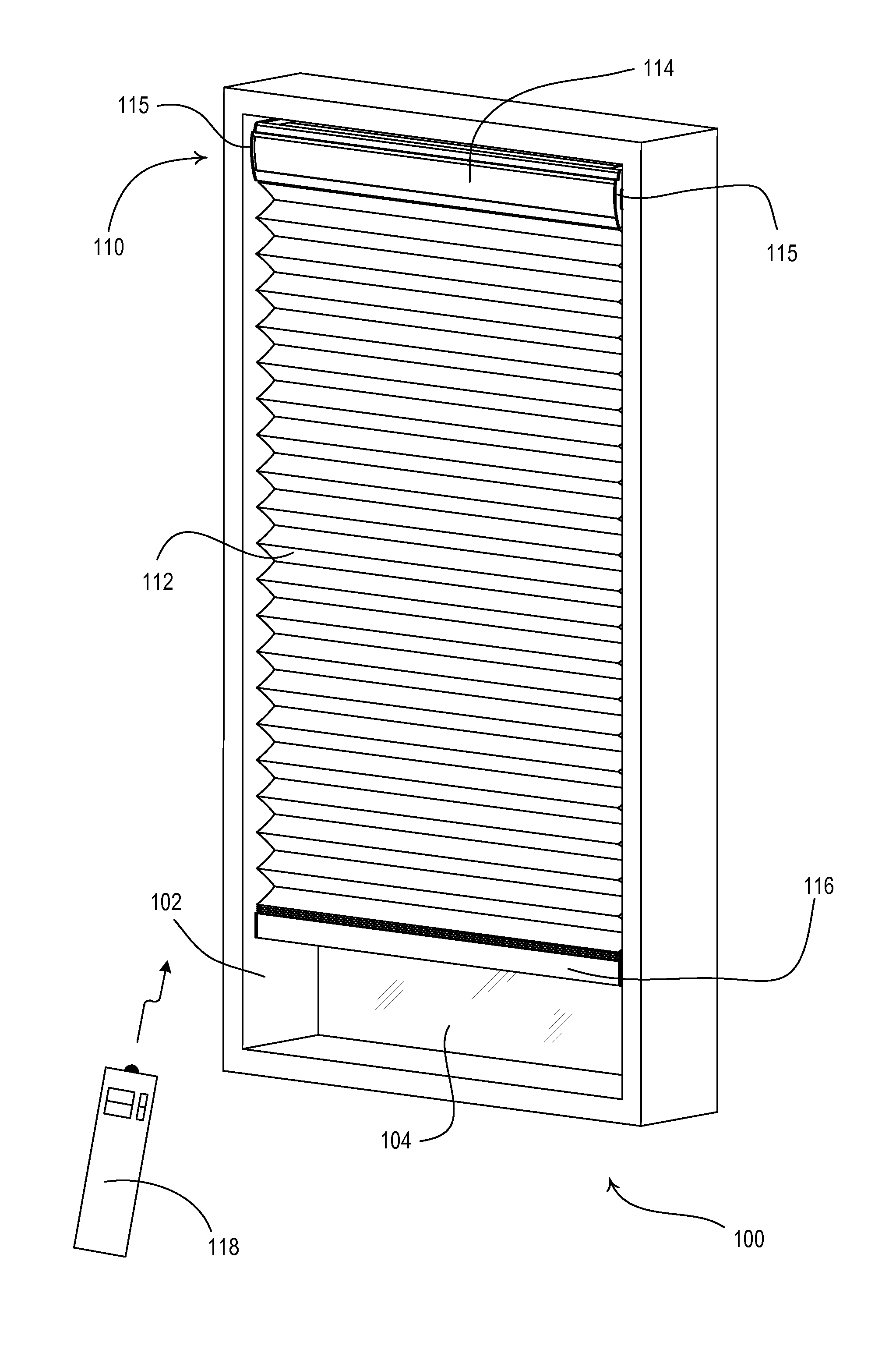
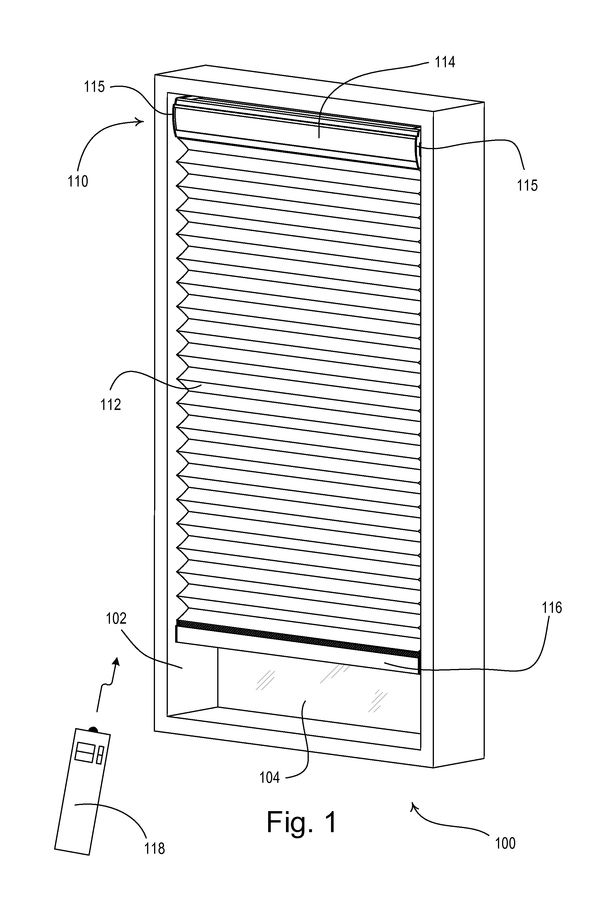
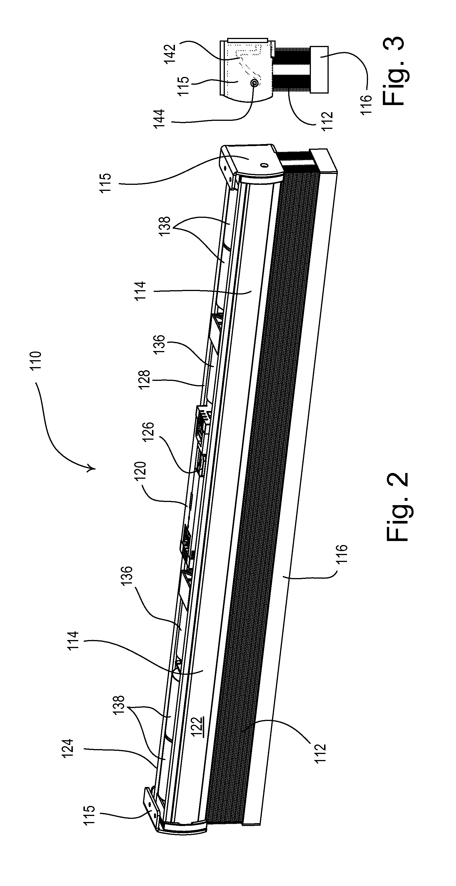
[0038]FIG. 1 is a perspective view of a motorized window treatment system 100 having a battery-powered motorized window treatment 110 mounted in an opening 102, for example, in front of a window 104 according to an embodiment of the present invention. The battery-powered motorized window treatment 110 comprises a covering material, for example, a cellular shade fabric 112 as shown in FIG. 1. The cellular shade fabric 112 has a top end connected to a headrail 114 (that extends be...


PUM


Abstract

A battery-powered motorized window treatment for covering at least a portion of a window may be adjusted into a service position to allow for access to at least one battery that is powering the motorized window treatment. A headrail of the motorized window treatment may be adjusted to the service position to allow for easy replacement of the batteries without unmounting the headrail and without requiring tools. The motorized window treatment may comprise brackets having buttons that may be actuated to release the headrail from a locked position, such that the head rail may be rotated into the service position. The headrail easily rotates through a controlled movement into the service position, such that a user only needs one free hand available to move the motorized window treatment into the service position and change the batteries.

Description

CROSS-REFERENCE TO RELATED APPLICATIONS[0001]This application is a non-provisional application of commonly-assigned U.S. Provisional Application No. 61 / 451,960, filed Mar. 11, 2011, and U.S. Provisional Application No. 61 / 530,799, filed Sep. 2, 2011, and U.S. Provisional Application No. 61 / 547,319, filed Oct. 11, 2011, all entitled MOTORIZED WINDOW TREATMENT, the entire disclosures of which are hereby incorporated by reference.BACKGROUND OF THE INVENTION[0002]1. Field of the Invention[0003]The present invention relates to a motorized window treatment, and more specifically, to a battery-powered motorized window blind system having a service position to allow for easy removal and installation of batteries.[0004]2. Description of the Related Art[0005]Motorized window treatments typically include a flexible fabric or other means for covering a window in order to block or limit the daylight entering a space and to provide privacy. The motorized window treatments may comprise roller shad...

Claims


Application Information

Patent Timeline
IPC IPC(8): A47H5/02A47H1/12
CPCE06B9/32E06B9/322E06B9/62E06B2009/2625E06B2009/6818E06B9/70Y02B80/50Y02B60/50H04W52/0238H04W52/0245H04W52/0287E06B2009/6872Y02B80/00Y02D30/70E06B9/68Y02A30/24H04W52/0216H04W52/0219H04W52/0229H04W52/028H04W52/0235H04W52/0225E06B9/38E06B9/72
Inventor BLAIR, EDWARD J.CHAMBERS, SAMUEL F.KIRBY, DAVID A.OGDEN, JR., PETER W.WILSON, JAMES J.ZERNHELT, JUSTIN M.
Owner LUTRON TECH CO LLC
Why Eureka
Try Eureka