Water electrolysis system and method of operating same

a water electrolysis and system technology, applied in the field of water electrolysis system and method of operating same, can solve the problems of reducing reducing and posing economic problems, so as to reduce the endurance time of the high-pressure device, increase the amount of hydrogen bubbles, and reduce the durability of the second back-pressure valve 8

Active Publication Date: 2012-10-11
HONDA MOTOR CO LTD
View PDF2 Cites 15 Cited by
  • Summary
  • Abstract
  • Description
  • Claims
  • Application Information

AI Technical Summary

Benefits of technology

[0013]When the second back-pressure valve 8 is opened to discharge the water in liquid phase from the pressure-resistant vessel 2 through the water drainage conduit 5a and the second back-pressure valve 8, the pressure of the discharged water abruptly drops. Therefore, a large load tends to be applied to the second back-pressure valve 8. As the differential pressure applied across a high-pressure device such as the second back-pressure valve 8 or the like increases, an increased amount of bubbles of hydrogen dissolved in the water is generated, greatly reducing the endurance time of the high-pressure device. A high differential pressure applied across the second back-pressure valve 8 is liable to damage the seals of the second back-pressure valve 8, resulting in a reduction in the durability of the second back-pressure valve 8.

Problems solved by technology

As the differential pressure applied across a high-pressure device such as the second back-pressure valve 8 or the like increases, an increased amount of bubbles of hydrogen dissolved in the water is generated, greatly reducing the endurance time of the high-pressure device.
A high differential pressure applied across the second back-pressure valve 8 is liable to damage the seals of the second back-pressure valve 8, resulting in a reduction in the durability of the second back-pressure valve 8.
Therefore, when the water is discharged under high pressure from the pressure-resistant vessel 2, a large amount of hydrogen is also discharged from the pressure-resistant vessel 2, posing economic problems.

Method used


Image

  • Water electrolysis system and method of operating same
  • Water electrolysis system and method of operating same
  • Water electrolysis system and method of operating same

Examples


first embodiment

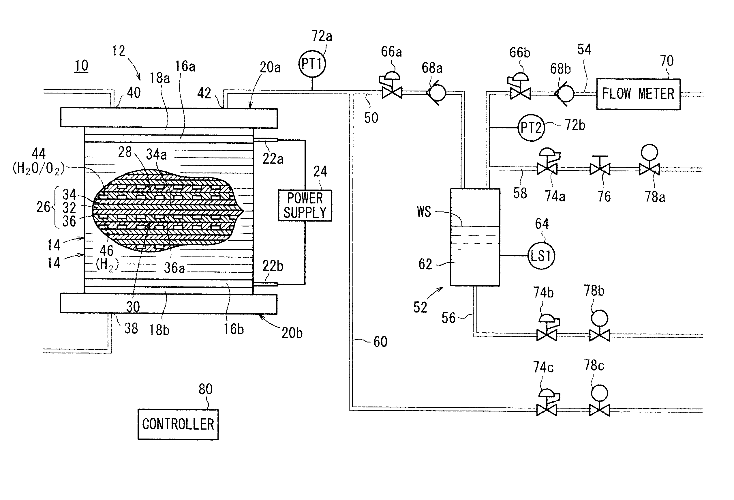
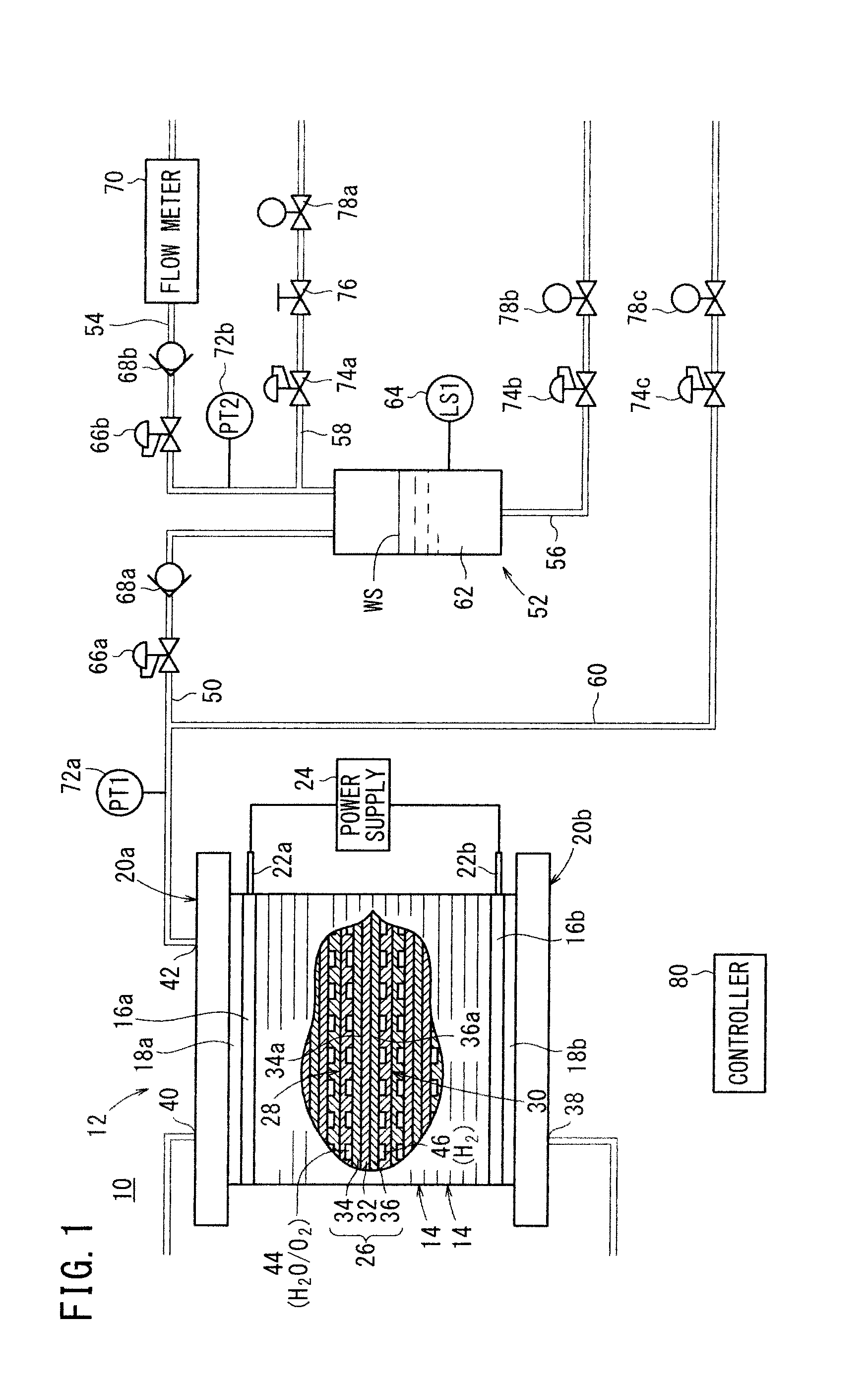
[0058]As shown in FIG. 1, a water electrolysis system 10 according to the present invention includes a differential-pressure-type water electrolysis apparatus (high-pressure hydrogen manufacturing apparatus) 12 which electrically decomposes water (pure water) to generate oxygen and high-pressure hydrogen having a pressure higher than an ordinary oxygen pressure, e.g., hydrogen having a pressure in the range from 1 MPa to 70 MPa.

[0059]The differential-pressure-type water electrolysis apparatus 12 has a cell unit comprising a stack of unit cells 14. The differential-pressure-type water electrolysis apparatus 12 also includes a terminal plate 16a, an insulating plate 18a, and an end plate 20a which are mounted on one end of the cell unit in a successive array outwardly in the order named, and a terminal plate 16b, an insulating plate 18b, and an end plate 20b which are mounted on another end of the cell unit in a successive array outwardly in the order named. The unit cells 14, the ter...

second embodiment

[0094]FIG. 6 is a schematic diagram of a water electrolysis system 90 according to the present invention.

[0095]Those parts of the water electrolysis system 90 according to the second embodiment which are identical to the water electrolysis system 10 according to the first embodiment are denoted by identical reference characters, and will not be described in detail below. The use of identical reference characters for identical parts also applies to third through eighth embodiments of the present invention to be described later.

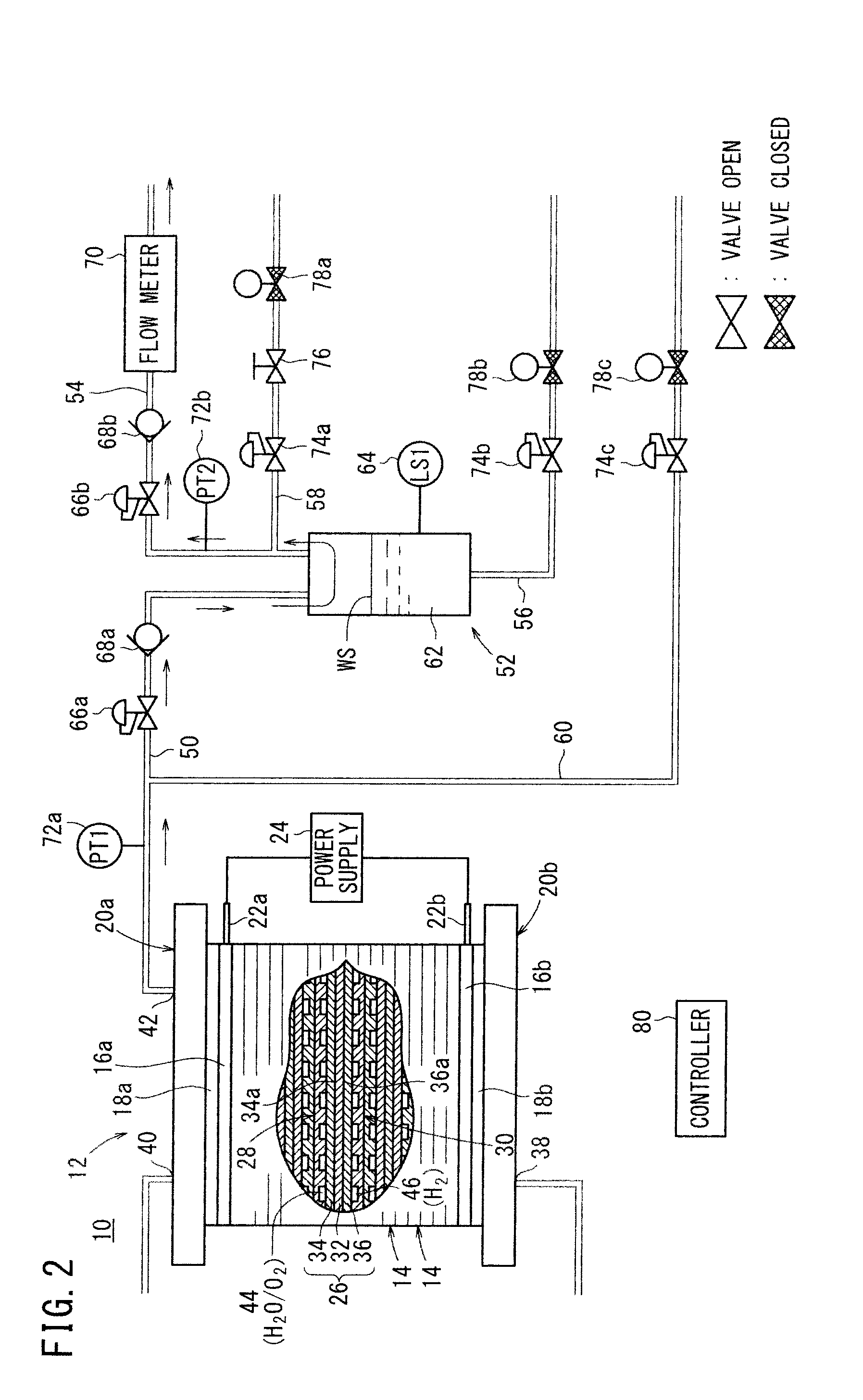
[0096]As shown in FIG. 6, a gas-liquid separator 52 has a tank 62 to which there is connected a gas depressurizing line 58 which depressurizes the gas in the gas-liquid separator 52 and which also depressurizes the water electrolysis apparatus. The gas depressurizing line 58 includes a first pressure reducing valve 74a and a first on-off valve 78a. The water electrolysis system 90 according to the second embodiment is free of the apparatus depressurizing line 6...

third embodiment

[0105]FIG. 8 is a schematic diagram of a water electrolysis system 100 according to the present invention.

[0106]Those parts of the water electrolysis system 100 according to the third embodiment which are identical to the water electrolysis system 10 according to the first embodiment and the water electrolysis system 90 according to the second embodiment are denoted by identical reference characters, and will not be described in detail below.

[0107]As shown in FIG. 8, a hydrogen pipe 50 is free of a back-pressure valve, but includes a first check valve 68a, and a high-pressure hydrogen outlet pipe 54 includes a back-pressure valve 66 and a second check valve 68b.

[0108]According to the third embodiment, the water electrolysis system 100 is controlled for its operation essentially in the same manner as with the water electrolysis system 90 according to the second embodiment. Specifically, when the gas in the gas-liquid separator 52 is depressurized, the residual pressure in the water ...


PUM

PropertyMeasurementUnit
pressureaaaaaaaaaa
pressureaaaaaaaaaa
pressureaaaaaaaaaa

Abstract

A water electrolysis system includes a water electrolysis apparatus for electrically decomposing water to generate oxygen and high-pressure hydrogen having a pressure higher than the oxygen, a gas-liquid separator connected to a hydrogen pipe which discharges the high-pressure hydrogen from the water electrolysis apparatus, for separating water contained in the high-pressure hydrogen, a high-pressure hydrogen outlet pipe for delivering the high-pressure hydrogen separated from water from the gas-liquid separator, a water drainage line for discharging the water from the gas-liquid separator, and a gas depressurizing line connected to the gas-liquid separator, for degassing the gas-liquid separator before the water is discharged from the water drainage line into the water drainage line.

Description

CROSS-REFERENCE TO RELATED APPLICATION[0001]This application is based upon and claims the benefit of priority from Japanese Patent Applications No. 2011-083946 filed on Apr. 5, 2011 and No. 2011-159762 filed on Jul. 21, 2011, of which the contents are incorporated herein by reference.BACKGROUND OF THE INVENTION[0002]1. Field of the Invention[0003]The present invention relates to a water electrolysis system including a water electrolysis apparatus for electrically decomposing water to generate oxygen and high-pressure hydrogen having a pressure higher than the oxygen, and a gas-liquid separator connected to a hydrogen pipe which discharges the high-pressure hydrogen from the water electrolysis apparatus, for separating water contained in the high-pressure hydrogen, and a method of operating such a water electrolysis apparatus.[0004]2. Description of the Related Art[0005]Generally, hydrogen is used as a fuel gas in a reaction to generate electric energy in fuel cells. The hydrogen is ...

Claims


Application Information

Patent Timeline
Patent Type & Authority Applications(United States)
IPC IPC(8): C25B1/12
CPCC25B1/12Y02E60/366C25B15/02C25B9/08Y02E60/36C25B1/04C25B9/05C25B9/19
Inventor TAKEUCHI, JUNNAKAZAWA, KOJINAGAOKA, HISASHIYOSHIDA, TETSUYAOKABE, MASANORIKURASHINA, DAISUKEMIYAKE, AOI
Owner HONDA MOTOR CO LTD
Why Eureka
Try Eureka