

Phosphor and light-emitting device
- Summary
- Abstract
- Description
- Claims
- Application Information
AI Technical Summary
Benefits of technology
Problems solved by technology
Method used
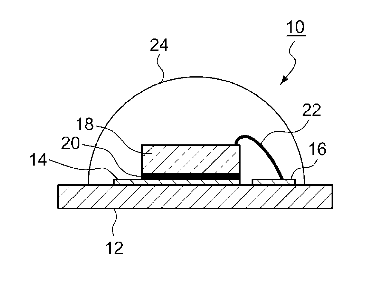
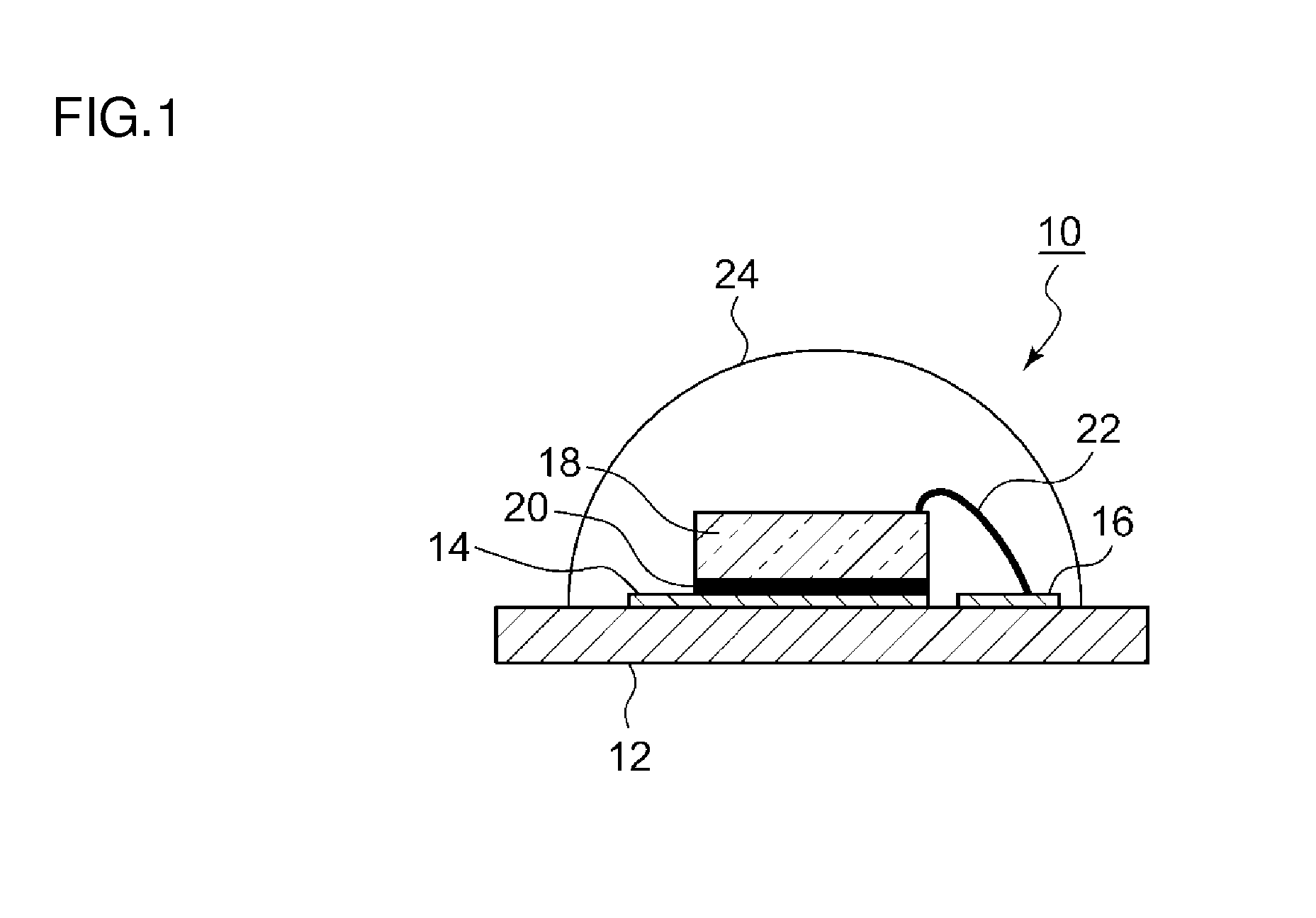
Image

Examples
examples
[0085]The above phosphor and the above light-emitting device are more specifically described below using examples. It will be understood that the raw materials for the phosphor and the light-emitting device, the production method, the chemical composition of the phosphor, and other features described below are not intended to limit embodiments of the phosphor and the light-emitting device according to the invention.
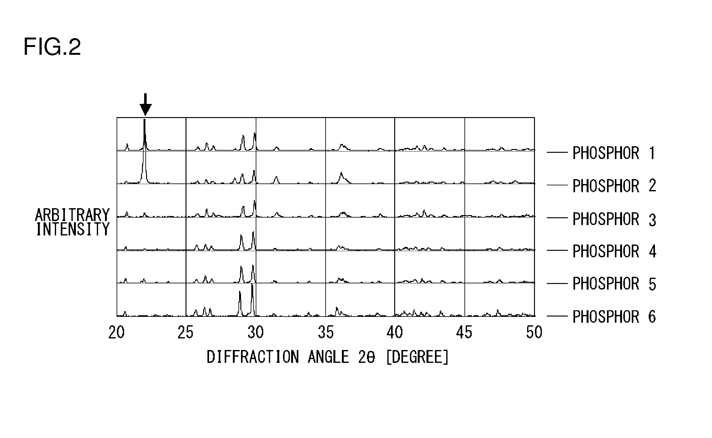
[0086]First, phosphors used in the light-emitting devices of the examples are described in detail.
[0087]
[0088]Phosphor 1 is a phosphor represented by (Ca0.6,Sr0.25,Eu0.15)7 / 6SiO3Cl2 / 6. Phosphor 1 is so synthesized as to have the general formula (M2x,M3y,M4z)mM1O3X2 / n, wherein M1=Si, M2=Ca, M3=Sr, X═Cl, M4=Eu2+, m=7 / 6, n=6, the contents x, y, and z of M2, M3, and M4 are 0.60, 0.25, and 0.15, respectively. In phosphor 1, cristobalite is produced, because SiO2 is added as a raw material in an excess mixing ratio. Phosphor 1 was produced as described below. First, the raw mat...
example
[0132]In this example, phosphors 1 and 13 were used as the first and second phosphors, respectively, and a light-emitting device was prepared using a phosphor paste containing a mixture of them. In this example, a phosphor mixture of phosphors 1 and 9 (2:1 in weight ratio) was used.
PUM
 Abstract
Description
Claims
Application Information