Light scanning device and image formation apparatus

Active Publication Date: 2012-10-11
SEIKO EPSON CORP
View PDF1 Cites 4 Cited by
  • Summary
  • Abstract
  • Description
  • Claims
  • Application Information

AI Technical Summary

Benefits of technology

[0006]An advantage of some aspects of the invention is that it provides a light scanning device and an image formation apparatus, in which even if the maximum deflection angle of a movable section is changed, the detection accuracy of the maximum deflection angle can be maintained.

Problems solved by technology

In this manner, in the apparatus described in JP-A-2003-131151, there is a problem in that a difference occurs in the detection accuracy of the maximum displacement angle, so that it is not possible to accurately detect and control turning (oscillation) of the galvano-mirror at the maximum displacement angle.

Method used


Image

  • Light scanning device and image formation apparatus
  • Light scanning device and image formation apparatus
  • Light scanning device and image formation apparatus

Examples


first embodiment

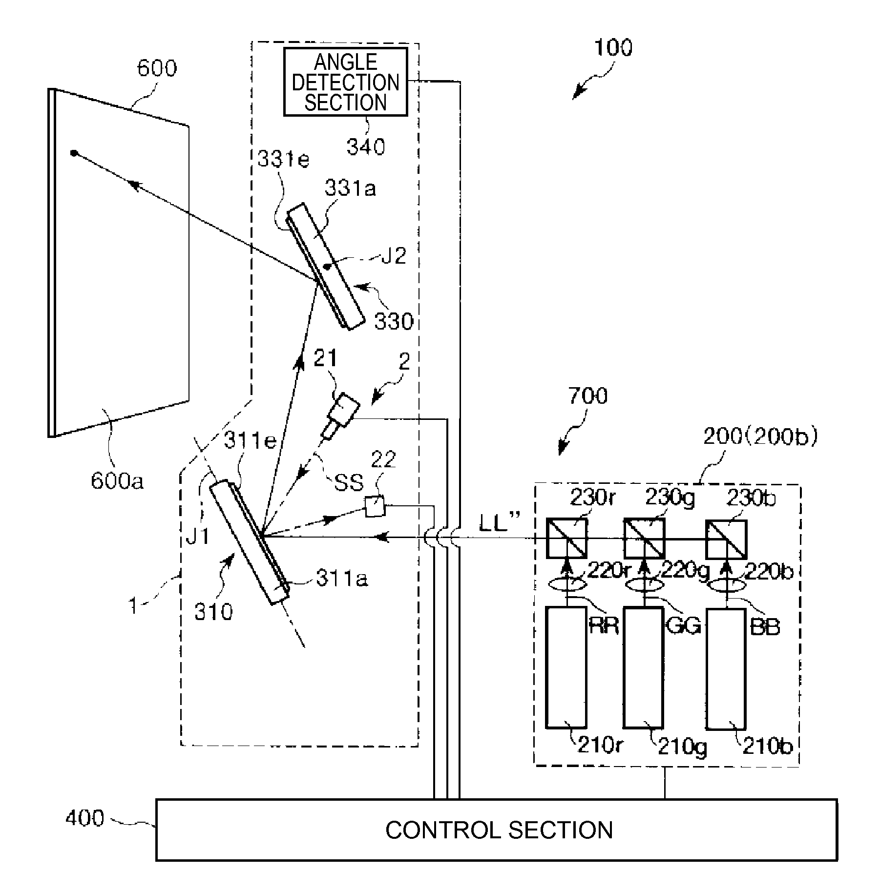
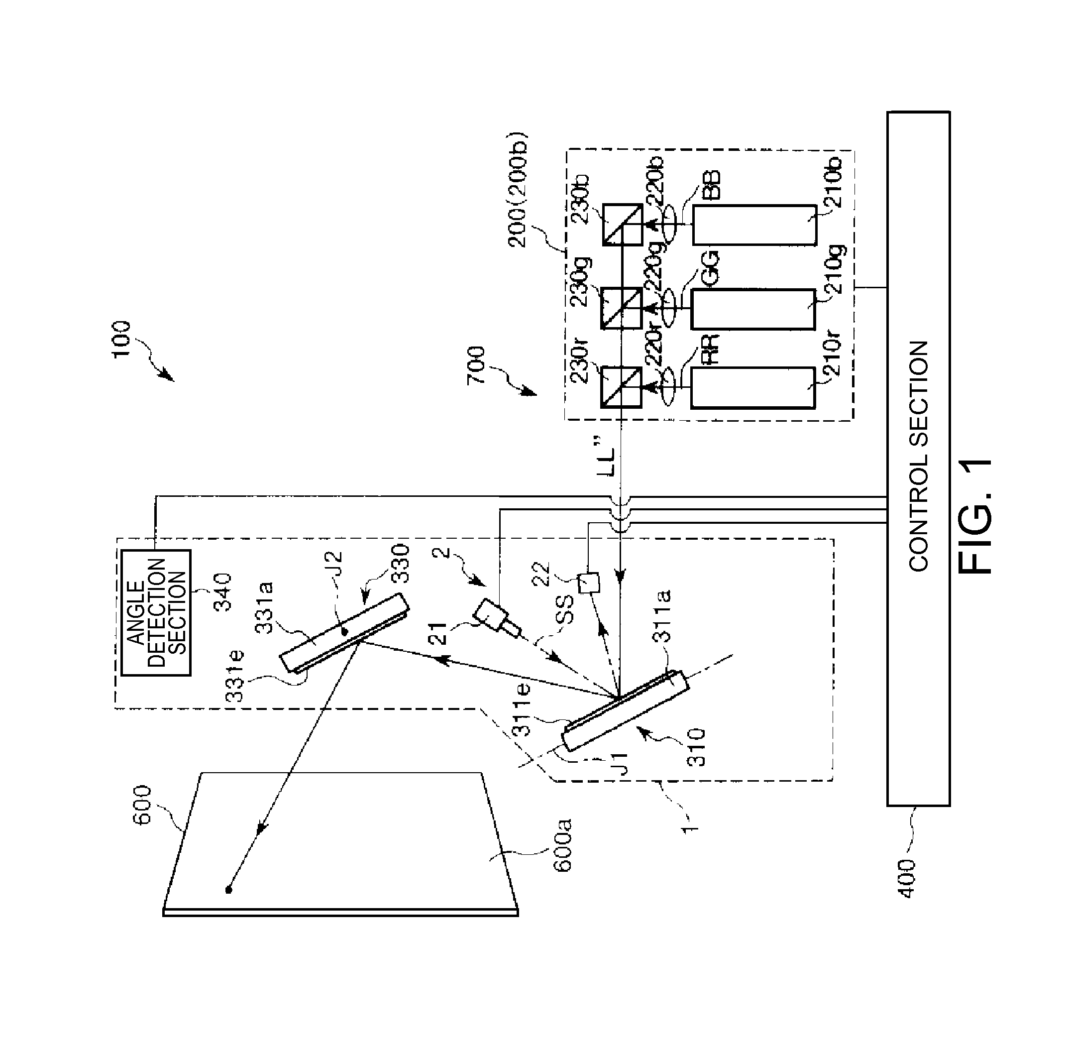
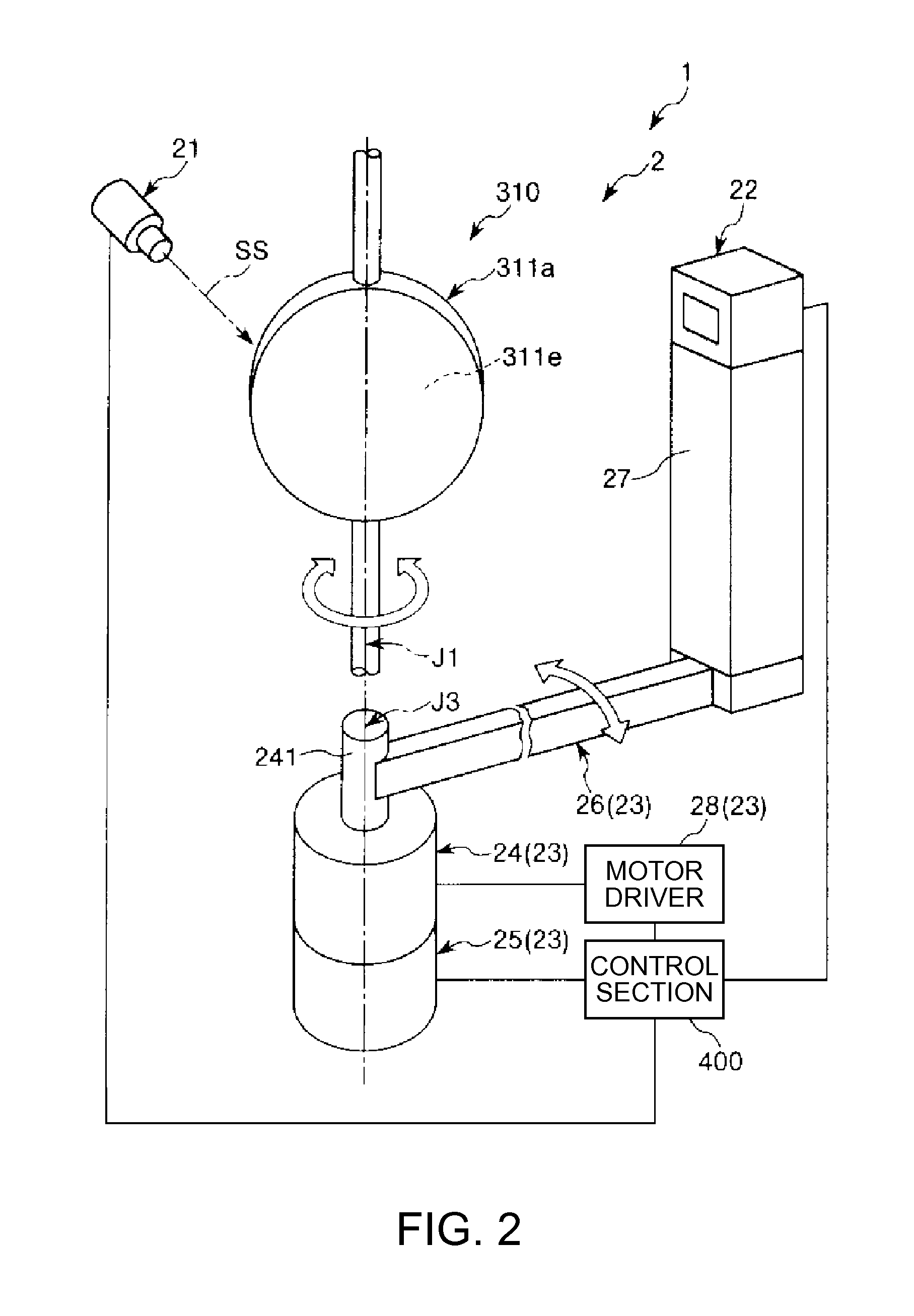
[0035]FIG. 1 is a diagram showing the schematic configuration of a projector which is included in an image forming apparatus (a first embodiment) according to the invention, FIG. 2 is a perspective view showing a light scanning device built into the projector shown in FIG. 1, and FIGS. 3 and 4 respectively are plan views showing operation states of the light scanning device shown in FIG. 2. In addition, in the following, for convenience of explanation, the upper side in FIG. 2 is referred to as a “top” or an “upside” and the lower side is referred to as a “bottom” or a “downside”.

[0036]An image forming apparatus 100 according to this embodiment shown in FIG. 1 includes a screen (a display object) 600 installed inside (indoors) a structure such as a building, for example, or outdoors, and a projector 700 which displays a given image such as a still image or a moving image on a display surface 600a formed in front of the screen 600.

[0037]The screen 600 is fixed to, for example, a wall...

second embodiment

[0065]FIG. 5 is a perspective view showing an image forming apparatus according to the second embodiment of the invention, FIG. 6 is a diagram showing the schematic configuration of a projector which is included in the image forming apparatus shown in FIG. 5, FIG. 7 is a cross-sectional view showing a screen (a display device) with which the image forming apparatus shown in FIG. 5 is provided, FIG. 8 is a graph showing the relationship between the transmittance of the screen shown in FIG. 7 and the intensity of voltage which is applied to a liquid crystal polymer composite layer, and FIGS. 9 and 10 respectively are diagrams showing operation states of the screen. In addition, in the following, for convenience of explanation, the upper side in FIGS. 5, 9, and 10 is referred to as a “top” or an “upside” and the lower side is referred to as a “bottom” or a “downside”. Further, the upper side in FIG. 7 is referred to as a “front (front face)” or a “front side” and the lower side is refe...


PUM


Abstract

A light scanning device includes: a movable section which has a light reflection section reflecting light and oscillates around an oscillating axis and in which a maximum deflection angle thereof is variable; and a detection section which detects the maximum deflection angle of the movable section, wherein the detection section includes a light source which irradiates light toward the light reflection section, a light-receiving section which receives reflected light of the light from the light source, reflected by the light reflection section, and a displacement drive section which changes a position of the light-receiving section in accordance with the maximum deflection angle of the movable section.

Description

BACKGROUND[0001]1. Technical Field[0002]The present invention relates to a light scanning device and an image formation apparatus.[0003]2. Related Art[0004]For example, as an apparatus which displays a desired image (for example, promotional advertising such as a commercial message) on a screen, an apparatus configured so as to scan the screen in a horizontal direction and a vertical direction with laser light emitted from a light source by using two galvano-mirrors is known (refer to JP-A-2003-131151, for example). Further, in an apparatus described in JP-A-2003-131151, a drive timing of each galvano-mirror is controlled on the basis of a detection signal of an optical sensor fixed on the screen. Further, the maximum displacement angle of the galvano-mirror can also be sought from the detection signal of the optical sensor.[0005]However, in the apparatus described in JP-A-2003-131151, in the case of changing the size of an image on the screen by changing the maximum displacement an...

Claims


Application Information

Patent Timeline
IPC IPC(8): H04N1/04G01B11/26
CPCH04N2201/04713G02B26/101H04N2201/04739
Inventor SHIMIZU, TAKESHIWAKABAYASHI, SHUICHI
Owner SEIKO EPSON CORP
Why Eureka
Try Eureka