Differential microphone with sealed backside cavities and diaphragms coupled to a rocking structure thereby providing resistance to deflection under atmospheric pressure and providing a directional response to sound pressure

Active Publication Date: 2012-10-11
BOARD OF RGT THE UNIV OF TEXAS SYST
View PDF10 Cites 15 Cited by
  • Summary
  • Abstract
  • Description
  • Claims
  • Application Information

AI Technical Summary

Benefits of technology

[0007]Furthermore, there is a desire to create a vacuum sealed microphone. By removing air from the gap, a microphone with much lower self-noise (which results in higher fidelity) can be fabricated with a potentially better frequency response. However, a very stiff diaphragm would be required

Problems solved by technology

Without a pressure release, it is challenging to design compliant membranes that do not collapse under atmospheric pressure.
However, most miniature microphones using MEMS processing use a deep reactive ion etch step through the entire silicon substrate, thereby preventing CMOS compatibility.
However, a very stiff diaphragm would be required to prevent the structure from collapsing under external atmospheric pressure, and such a structure would have poor sensitivity to small sound pressure due to its stiffness.
Such structures have been manufactured using MEMS processing to realize ultrasound sensors but not functional microphones.

Method used


Image

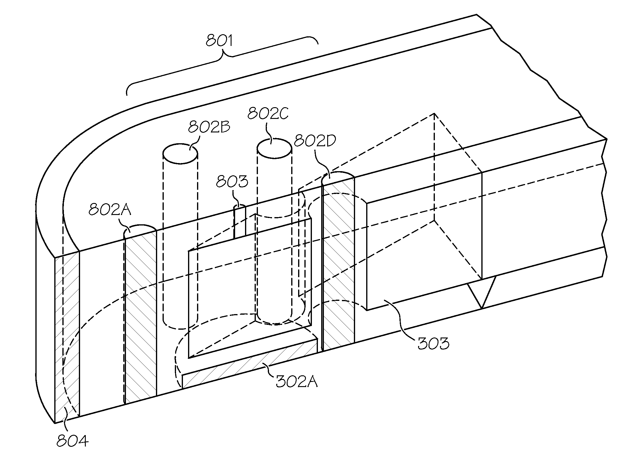
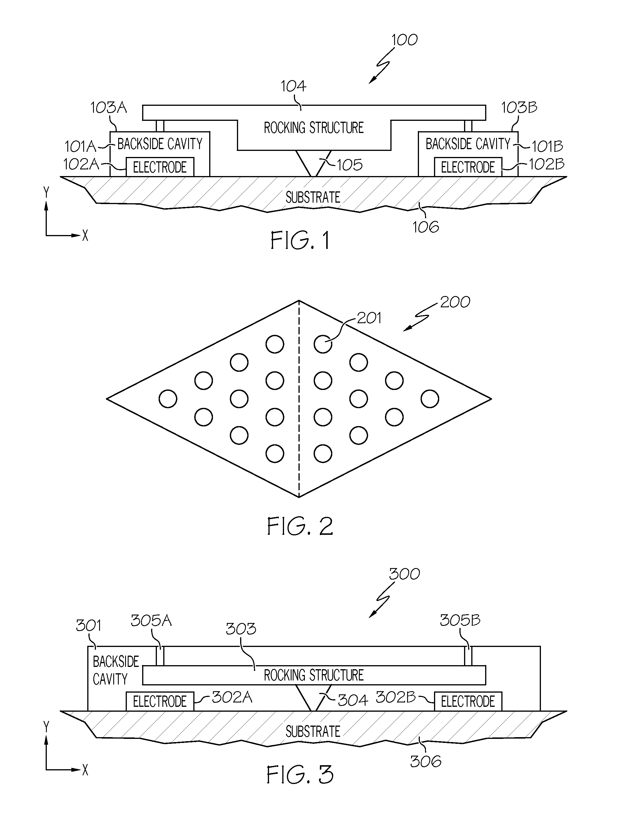
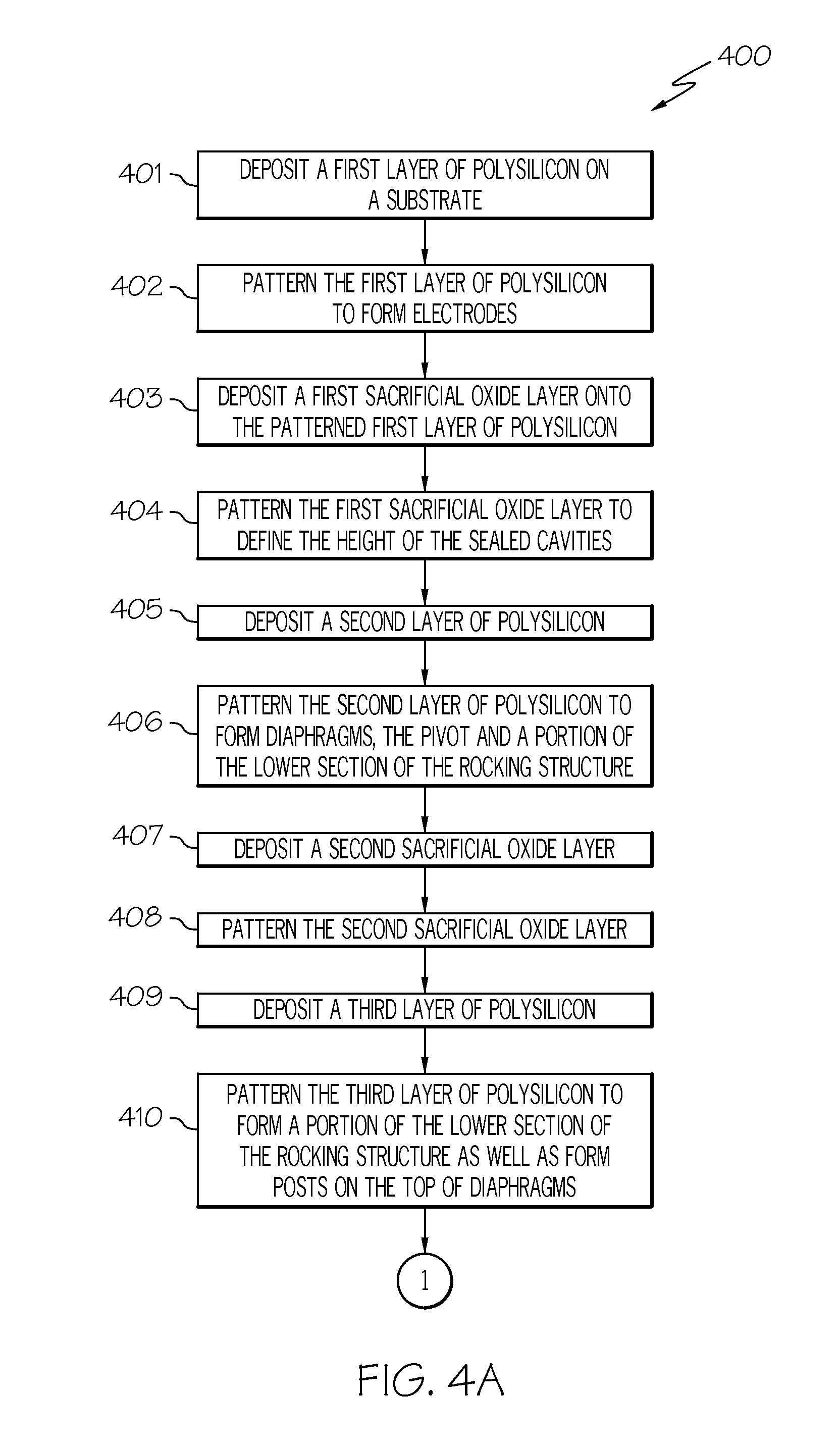
  • Differential microphone with sealed backside cavities and diaphragms coupled to a rocking structure thereby providing resistance to deflection under atmospheric pressure and providing a directional response to sound pressure
  • Differential microphone with sealed backside cavities and diaphragms coupled to a rocking structure thereby providing resistance to deflection under atmospheric pressure and providing a directional response to sound pressure
  • Differential microphone with sealed backside cavities and diaphragms coupled to a rocking structure thereby providing resistance to deflection under atmospheric pressure and providing a directional response to sound pressure

Examples


Embodiment Construction

[0023]In the following description, numerous specific details are set forth to provide a thorough understanding of the present invention. However, it will be apparent to those skilled in the art that the present invention may be practiced without such specific details.

[0024]As stated in the Background section, recently, microelectromechanical systems (MEMS) processing has been used to fabricate miniature microphones. However, most miniature microphones using MEMS processing use the deep reactive ion through-wafer etch step thereby preventing CMOS compatibility. If, however, miniature microphones could use MEMS processing without the use of the through-wafer deep reactive ion etch step, then miniature microphones could be manufactured with CMOS compatible processes which have a significant cost advantage over other processes. Furthermore, there is a desire to create a vacuum sealed microphone. By removing air from the gap, a microphone with much lower self-noise (which results in hig...


PUM


Abstract

A vacuum sealed directional microphone and methods for fabricating said vacuum sealed directional microphone. A vacuum sealed directional microphone includes a rocking structure coupled to two vacuum sealed diaphragms which are responsible for collecting incoming sound and deforming under sound pressure. The rocking structure's resistance to bending aids in reducing the deflection of each diaphragm under large atmospheric pressure. Furthermore, the rocking structure exhibits little resistance about its pivot thereby enabling it to freely rotate in response to small pressure gradients characteristic of sound. The backside cavities of such a device can be fabricated without the use of the deep reactive ion etch step thereby allowing such a microphone to be fabricated with a CMOS compatible process.

Description

CROSS-REFERENCE TO RELATED APPLICATIONS[0001]This application is related to the following commonly owned co-pending U.S. patent application:[0002]Provisional Application Ser. No. 61 / 473,217, “Differential Microphone with Sealed Backside Cavities and Diaphragms Coupled to a Rocking Structure Thereby Providing Resistance to Deflection Under Atmospheric Pressure and Providing a Directional Response to Sound Pressure,” filed Apr. 8, 2011, and claims the benefit of its earlier filing date under 35 U.S.C. §119(e).GOVERNMENT INTERESTS[0003]This invention was made with government support under DC009721 awarded by the National Institutes of Health. The U.S. Government has certain rights in the invention.TECHNICAL FIELD[0004]The present invention relates generally to miniature microphones, and more particularly to a micromachined differential microphone with sealed backside cavities where the diaphragms are coupled to a rocking structure thereby providing resistance to deflection under extern...

Claims


Application Information

Patent Timeline
IPC IPC(8): H04R1/02H04R31/00
CPCH04R23/00
Inventor HALL, NEAL A.KUNTZMAN, MICHAEL LOUISKIRK, KAREN DENISE
Owner BOARD OF RGT THE UNIV OF TEXAS SYST
Why Eureka
Try Eureka