Radio base station, and communication control method

a radio base station and communication control technology, applied in power management, radio transmission, electrical equipment, etc., can solve the problems of reducing the connection rate of the radio base station, the decrement of the communication speed of the radio terminal, and the rejection of the base station, so as to reduce the load of the radio communication, and the quality of the communication servi

Inactive Publication Date: 2012-10-11
KYOCERA CORP
View PDF2 Cites 9 Cited by
  • Summary
  • Abstract
  • Description
  • Claims
  • Application Information

AI Technical Summary

Benefits of technology

[0015]The present invention enables a reduction in the load for the radio communicatio

Problems solved by technology

The conventional communication regulation method described above, however, has a high possibility that the radio base station will reject new radio communications, i.e., a high possibility of a handover failure, and the connection rate in this radio base station thus decreases.
Moreover, as the number of radio terminals in the cell increases, the communication speed of the radio terminals decreases so much that a buffer storing downlink transmission data (downlink buffer) in the radio base station

Method used


Image

  • Radio base station, and communication control method
  • Radio base station, and communication control method
  • Radio base station, and communication control method

Examples


Embodiment Construction

[0023]Next, an embodiment of the present invention will be described with reference to the drawings. To put it specifically, a description will be given of (1) Configuration of Radio Communication System, (2) Operation of Radio Base Station, (3) Operation and Effects, and (4) Other Embodiment. Note that, in the following description of the drawings of the embodiment below, the same or similar reference signs denote the same or similar portions.

[0024](1) Configuration of Radio Communication System

[0025]First, a description will be given of a configuration of a radio communication system according to the embodiment of the present invention in order of (1.1) Overall Schematic Configuration of Radio Communication System and (1.2) Configuration of Radio Base Station.

[0026](1.1) Overall Schematic Configuration of Radio Communication System

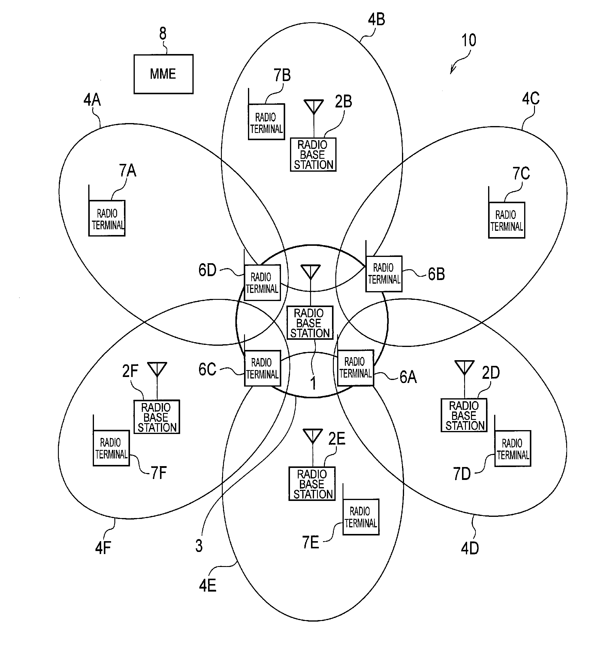
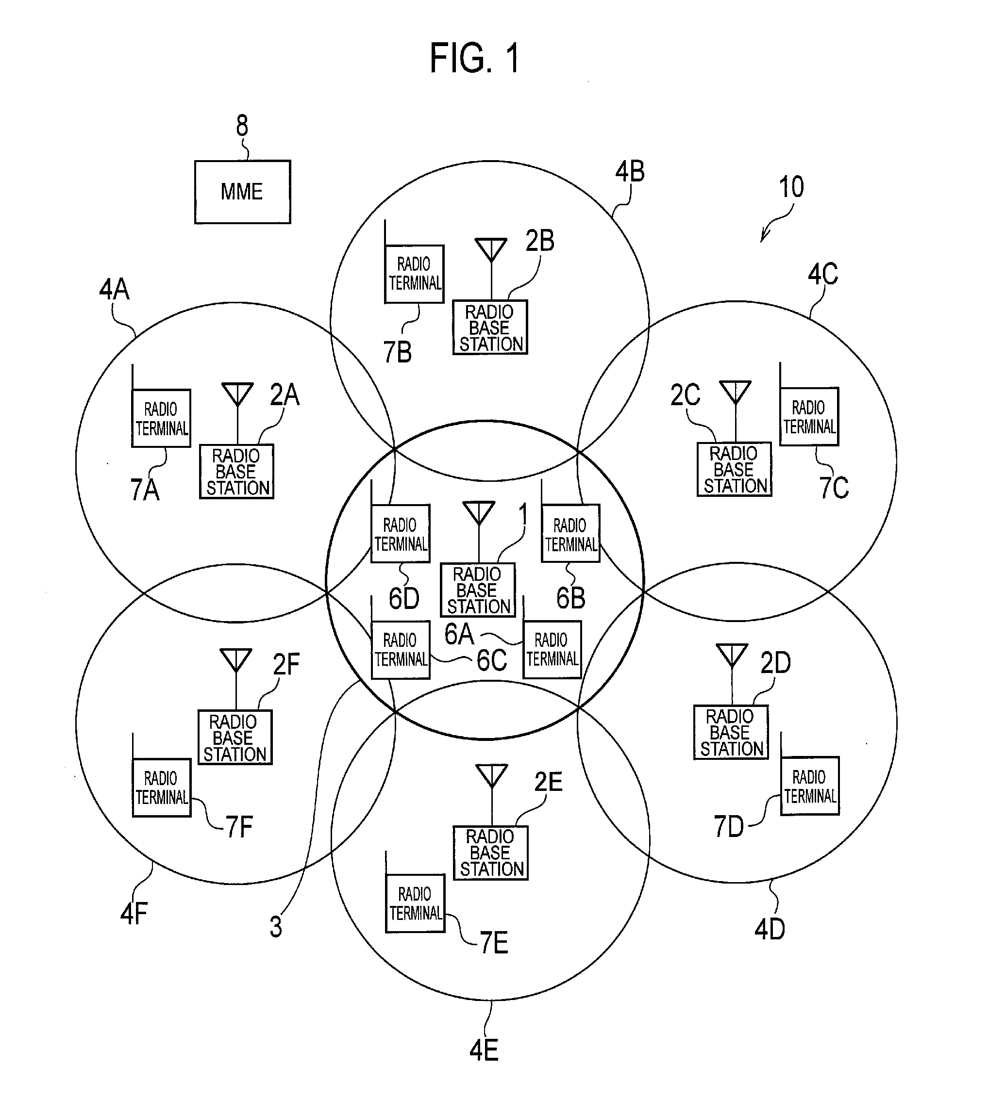
[0027]FIG. 1 is an overall schematic configuration diagram of a radio communication system 10 according to the embodiment of the present invention.

[0028...


PUM


Abstract

A radio base station (1) measures the volume of communication with radio terminals connected to said radio base station (1), and if said volume of communication exceeds a threshold value, the radio signal transmission power of the base station is decreased, and a request is made to other radio base stations to increase the radio signal transmission power of said other radio base stations.

Description

TECHNICAL FIELD[0001]The present invention relates to a radio base station configured to establish a connection with a radio terminal whose connection destination is determined in accordance with a received power and also relates to a communication control method in the radio base station.BACKGROUND ART[0002]In radio communication systems including radio base stations and radio terminals, one of neighboring radio base stations is determined as a connection destination of a radio terminal in accordance with received powers of radio signals from the radio base stations.[0003]In a case where radio communications performed by radio terminals existing in a cell that is the communication area provided by a radio base station become equal to or greater than the capacity of the radio base station, the radio base station regulates the communications to reduce the load for the radio communications (refer to Patent Document 1, for example).PRIOR ART DOCUMENTPatent Document[0004]PATENT DOCUMENT...

Claims


Application Information

Patent Timeline
IPC IPC(8): H04W52/34
CPCH04W16/08H04W52/04H04W52/343
Inventor ASAOKA, SUSUMUNAKANO, SHINJI
Owner KYOCERA CORP
Why Eureka
Try Eureka