
Pallet foot, a pallet and a box provided with feet and also a method for attaching a pallet foot to a platform

a technology of pallets and platforms, which is applied in the field of pallets, can solve the problems of heavy, difficult to handle, back injuries of users when lifting or moving, and the cost of pallets is both relatively high, and achieves the effect of simple and effective methods

Inactive Publication Date: 2012-10-18
SPARSORS PLAST
View PDF14 Cites 5 Cited by
  • Summary
  • Abstract
  • Description
  • Claims
  • Application Information

AI Technical Summary

Benefits of technology

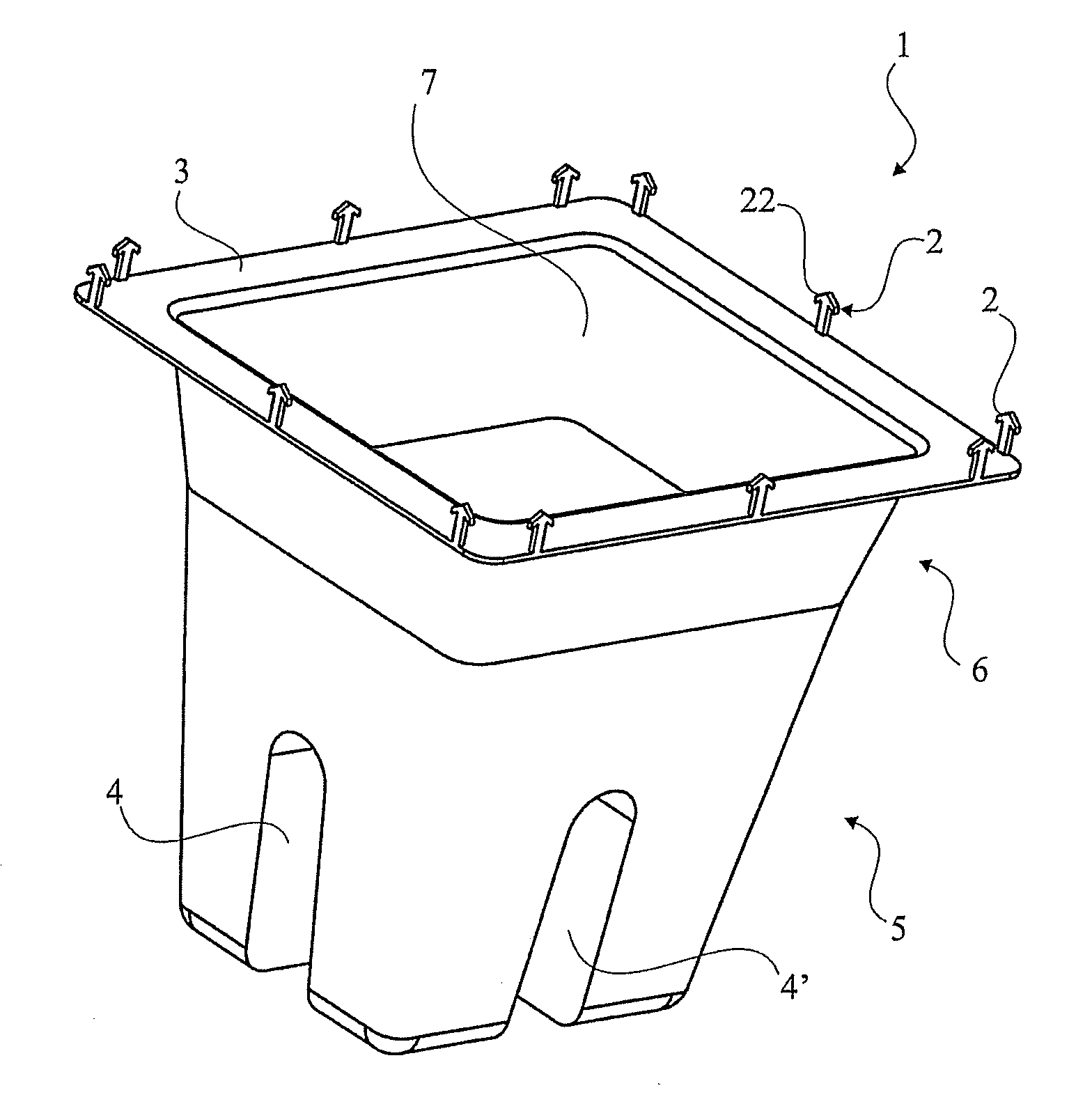
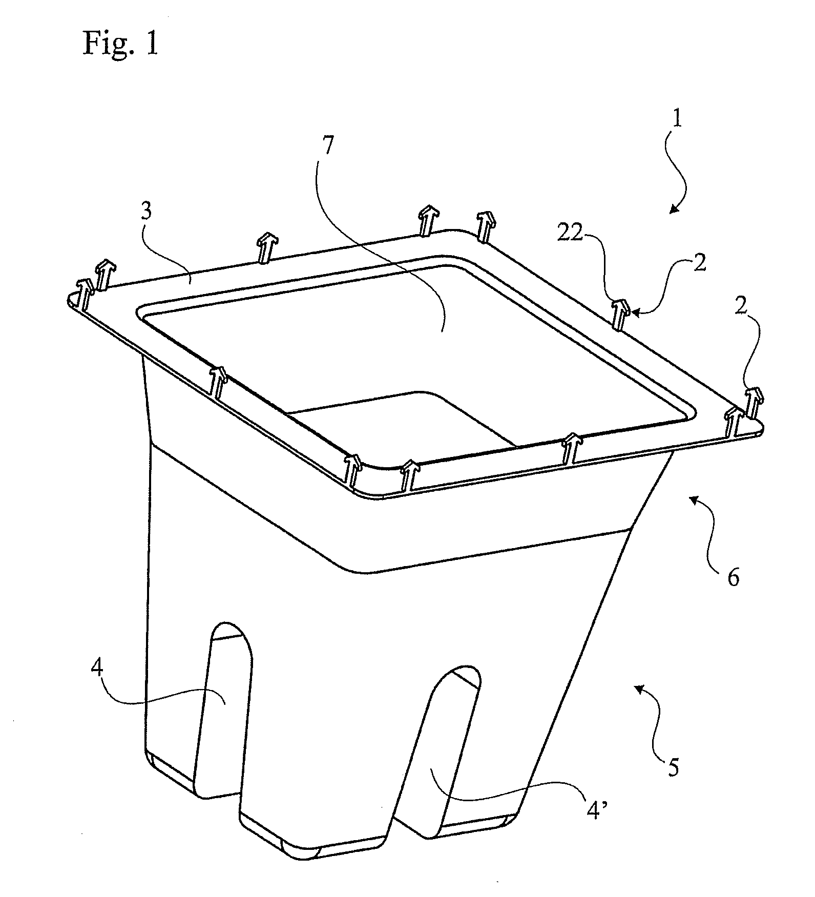
The invention is a pallet foot that can be attached to a penetrable platform, such as a sheet of paper or the bottom of a paper box. The pallet foot has a hollow shape with attachment members that can penetrate the platform. The attachment members are perpendicular to the stopping surface of the platform, ensuring a stable attachment. The pallet foot can be made from cardboard or plastic, and it is lightweight and recyclable. The lower portion of the pallet foot has grooves that match stabilizing beam members, making it easy to attach to a beam. The technical effects of the invention are a simple and cost-effective way to construct a pallet that can be attached to any platform, and it provides a lightweight and recyclable construction.

Problems solved by technology

As they are frequently made out of wooden material, pallets are both relatively expensive to manufacture, and heavy.
Their considerable weight means they are hard to handle and may cause back-injuries to a user upon lifting or moving it.
Another disadvantage coming with a wooden pallet is that the fork of a fork lift truck can enter the pallet from one direction only.
Also, during transports pallets represent a large proportion of the total weight resulting in undesirable high fuel consumptions.
The aforementioned pallet support structures are made out of plastic which is undesirable from an environmental point of view.
If gluing is done in dirty or dusty environment it may occur that such dirt or dust gets in between the adhesive surface and the cardboard leading to insufficient fixation.
In damp, wet or hot environments it might also occur that the adhesive comes loose of the cardboard and the pallet foot detaches.

Method used


Image

  • Pallet foot, a pallet and a box provided with feet and also a method for attaching a pallet foot to a platform
  • Pallet foot, a pallet and a box provided with feet and also a method for attaching a pallet foot to a platform
  • Pallet foot, a pallet and a box provided with feet and also a method for attaching a pallet foot to a platform

Examples


Embodiment Construction

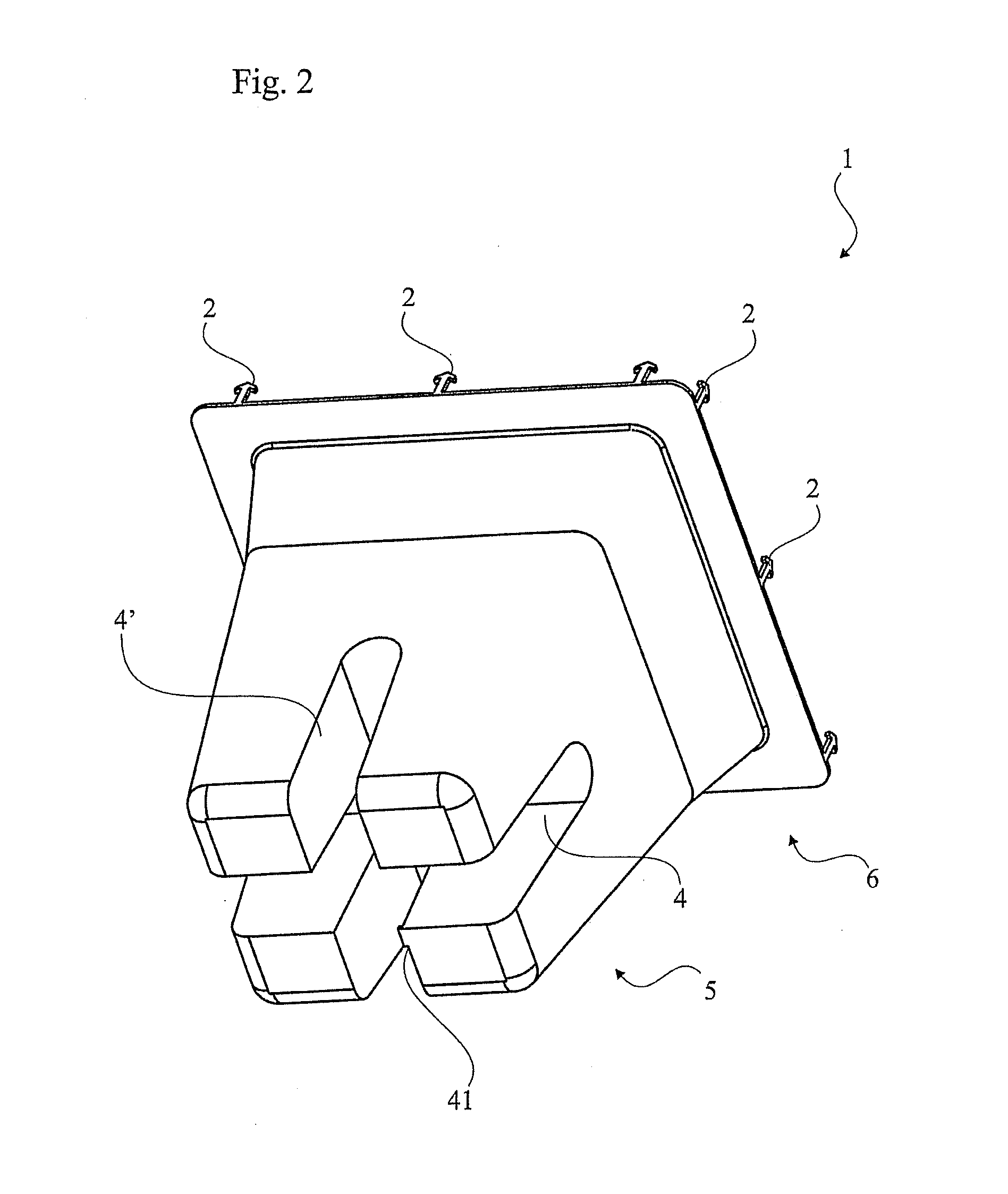
[0036]FIGS. 1-4 show a pallet foot 1 according to a preferred embodiment of the present invention, having an overall tapered and hollow shape. The wider upper base 6 of the pallet foot 1 presents an opening 7 surrounded by a stopping surface in the form of a horizontal flanged edge 3 for meeting the surface of an underside 81 of a platform 8 (see FIGS. 7a-b), where a platform for instance might be in the form of a cardboard sheet or other penetrable, rigid paper material suitable for constituting the platform of a pallet.

[0037]It is understood that the terms “horizontally” and “vertically” is to be put in relation to a platform 8 onto which a pallet foot 1 is to be attached. Horizontal then refers to the plane which is defined by such a platform 8, and vertical refers to a direction perpendicular to the plane which is defined by the platform 8.

[0038]The horizontal flanged edge 3 comprises a plurality of substantially vertically protruding attachment members 2 for penetrating said pl...


PUM

PropertyMeasurementUnit
widthaaaaaaaaaa
widthaaaaaaaaaa
widthaaaaaaaaaa

Abstract

The following invention relates to a pallet foot of overall hollow shape for being fixed on the back of a platform, where the base of the pallet foot has a horizontal flanged edge for meeting the surface of the back of the platform wherein said horizontal flanged edge comprises a plurality of substantially vertically protruding attachment members for penetrating said platform. The application also includes a pallet and a box provide with feet and also a method for attaching a pallet foot to a platform.

Description

TECHNICAL FIELD[0001]The present invention relates to a pallet foot of overall hollow and tapered shape for being fixed on the back of a platform, where the widest open base of the pallet foot has a horizontal flanged edge for meeting the surface of the back of said platform. Further, the present invention relates to a method for fixating a pallet foot onto a platform.BACKGROUND ART[0002]Pallets of various kinds are commonly used within transporting as well as for storing of goods. As they are frequently made out of wooden material, pallets are both relatively expensive to manufacture, and heavy. Their considerable weight means they are hard to handle and may cause back-injuries to a user upon lifting or moving it. Another disadvantage coming with a wooden pallet is that the fork of a fork lift truck can enter the pallet from one direction only. Also, during transports pallets represent a large proportion of the total weight resulting in undesirable high fuel consumptions. For these...

Claims


Application Information

Patent Timeline
Patent Type & Authority Applications(United States)
IPC IPC(8): B65D19/40B23P11/00
CPCB65D19/0026Y10T29/49833B65D19/40B65D2519/00019B65D2519/00054B65D2519/00069B65D2519/00089B65D2519/00104B65D2519/00273B65D2519/00288B65D2519/00323B65D2519/00333B65D2519/00338B65D2519/00373B65D2519/00567B65D2519/00776B65D2519/0084Y10T16/209B65D19/0028
Inventor NIELSEN, BIRGER
Owner SPARSORS PLAST
Learn More