Steering locking device

Inactive Publication Date: 2012-10-18
ALPHA +1
View PDF9 Cites 11 Cited by
  • Summary
  • Abstract
  • Description
  • Claims
  • Application Information

AI Technical Summary

Benefits of technology

[0017]According to the second aspect, an auxiliary lock assembly body constituted of the sliding plate and the closure member is assembled by using the assembling jig. In this assembled state, the auxiliary locking member is arranged in the auxiliary lock accommodating hole, the cover is attached to the housing, and then the assembling jig is pulled out. This enables t

Problems solved by technology

Thus, the locking member 102 requires a large size, and components are difficult to arrange in a limited space.
In addition, since the auxiliary locking member 104 is likely to

Method used


Image

  • Steering locking device
  • Steering locking device
  • Steering locking device

Examples


first embodiment

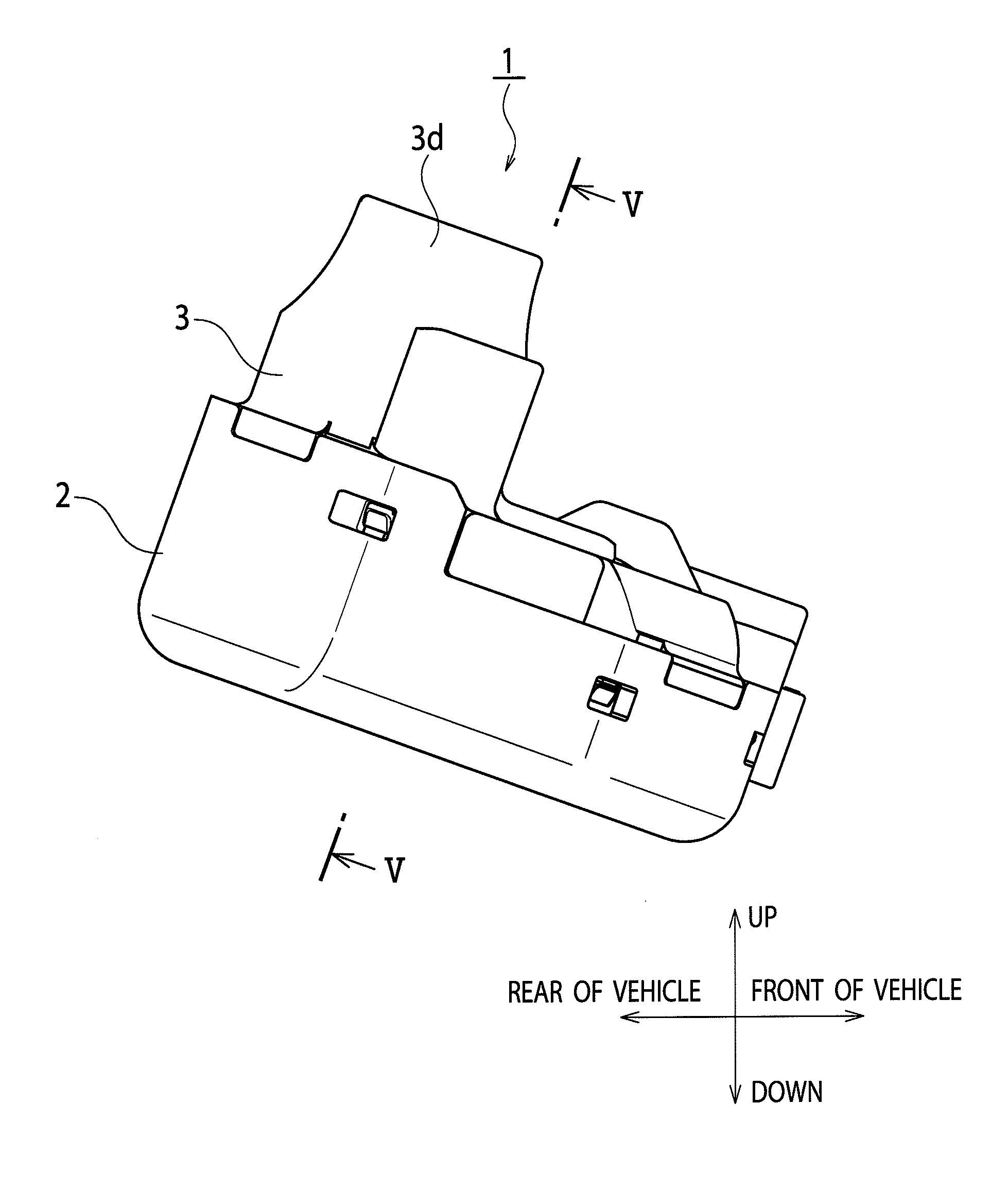
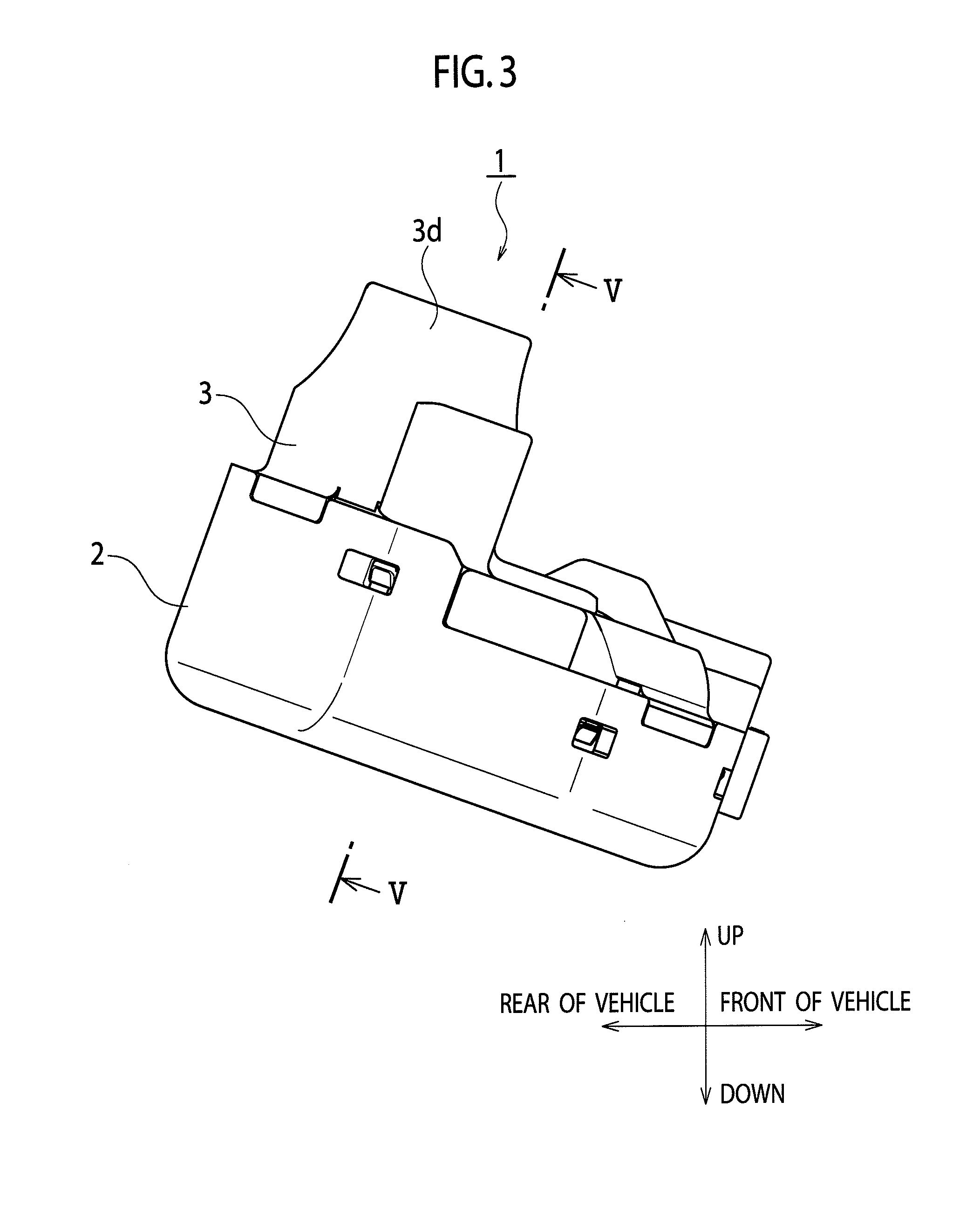
[0038]As shown in FIGS. 3 to 12, a steering locking device 1 of First Embodiment includes a cover 2 and a housing 3 which are attached to each other and is attached to a steering column device A accommodating an unillustrated steering shaft of an automobile.

[0039]The housing 3 includes a component accommodating chamber 3a, a lock accommodating hole 3b, and an auxiliary lock accommodating hole 3c which are formed inside the housing 3, and has a pair of leg portions 3d, 3d. The component accommodating chamber 3a is opened toward one side of the steering locking device 1 (a lower side in FIGS. 5, 6, and the like). The lock accommodating hole 3b penetrates the housing 3 from a bottom portion of the component accommodating chamber 3a to the steering column device A side and extends in a vertical direction with respect to an axial direction of the steering shaft. The auxiliary lock accommodating hole 3c extends in a direction orthogonal to the lock accommodating hole 3b. The pair of legs ...

second embodiment

[0066]FIG. 14 shows Second Embodiment of the present invention and is a cross-sectional view showing a steering lock device.

[0067]In a steering locking device 1A in Second Embodiment, the coupling portion 73 of the hanger 7 has a swelling-out portion 73a formed by swelling out of the hanger 7 toward both sides thereof, the arm portions 81, 82 of the lock main body 8 have bent ends 81b, 82b protruding in directions of approaching to each other, and the lock main body 8 is movably coupled to the hanger 7. The bent ends 81b, 82b can lock the swelling-out portion 73a of the hanger 7. The locking member 6 has the wide face B parallel to the axial direction of the steering shaft and the thick face C (the side face of the arm portion 74) perpendicular to the wide face B. The thick face C is provided with an engagement pin 79 as a protrusion engaged with the sliding plate 91. As compared with the steering locking device 1 in First Embodiment, the configuration is the same as that in First E...

third embodiment

[0070]FIG. 15 shows Third Embodiment of the present invention and is a cross-sectional view showing a steering locking device.

[0071]In a steering locking device 1B in Third Embodiment, a protrusion 74b engaged with the sliding plate 91 is provided on a side face of the arm portion 74 of the hanger 7. As compared with the steering locking device 1A in Second Embodiment, the configuration is the same as that in Second Embodiment except the protrusion 74b. Parts in the same configuration as that in Second Embodiment are denoted by the same reference numerals in the drawings, and descriptions thereof will be omitted.

[0072]In the aforementioned configuration, when the cover 2 is removed from the housing 3 in the locked state, the holding portion 21 of the cover 2 is disengaged from the sliding plate 91, and the sliding plate 91 is urged in the direction to the hanger 7. Thus, the sliding plate 91 becomes engaged with the protrusion 74b of the hanger 7. This prevents the movement of the h...


PUM


Abstract

A steering locking device (1, 1A, 1B, 1C) includes: a locking member (6) including a first face (B) parallel to an axial direction of a steering shaft, a second face (C) perpendicular to the first face (B), and a protrusion (62) protruding from the second face (B); and a sliding plate (91) extending from the first face (B) in a plate thickness direction (D) of the locking member (6), arranged outside the first face (B), and engageable with the protrusion (62).

Description

TECHNICAL FIELD[0001]The present invention relates to a steering locking device configured to lock rotation of a steering shaft of an automobile.BACKGROUND ART[0002]Patent Document 1 discloses a steering locking device of the related art. As shown in FIGS. 1 and 2, a steering locking device 100 includes a locking member 102, a driving body 103, and an auxiliary locking member 104. The locking member 102 is urged by a coil spring 101 in a direction to an unillustrated steering shaft of an automobile (an upward direction in FIGS. 1 and 2), and is fittable to the steering shaft. The driving body 103 is configured to drive the locking member 102. The auxiliary locking member 104 is arranged near the locking member 102 and capable of locking the locking member 102 at a locked position. The driving body 103 includes a rotating member 106 and a cam member 107. The rotating member 106 is configured to be driven by a motor 105 via an unillustrated worm. The cam member 107 is configured to be...

Claims


Application Information

Patent Timeline
IPC IPC(8): B60R25/02E05B65/12B60R25/021E05B17/20B60R25/0215B60R25/022B60R25/023E05B83/00
CPCB60R25/02153Y10T70/565Y10T70/5664Y10T70/5956
Inventor OKADA, TAKAHIROSAKANO, TAKESHIHAYASHI, KENJIROU
Owner ALPHA
Why Eureka
Try Eureka