
Variable-Elastomer Semi-Active Damping Apparatus

a semi-active, elastic technology, applied in mechanical devices, shock absorbers, transportation and packaging, etc., can solve the problems of increasing the damping force, increasing the fluid flow restriction, inducing a large amount of coulomb friction, etc., to reduce the cross-sectional area, increase the flow resistance, and reduce the axial distance

Inactive Publication Date: 2012-10-18
RODENBECK PHILLIP D
View PDF2 Cites 7 Cited by
  • Summary
  • Abstract
  • Description
  • Claims
  • Application Information

AI Technical Summary

Benefits of technology

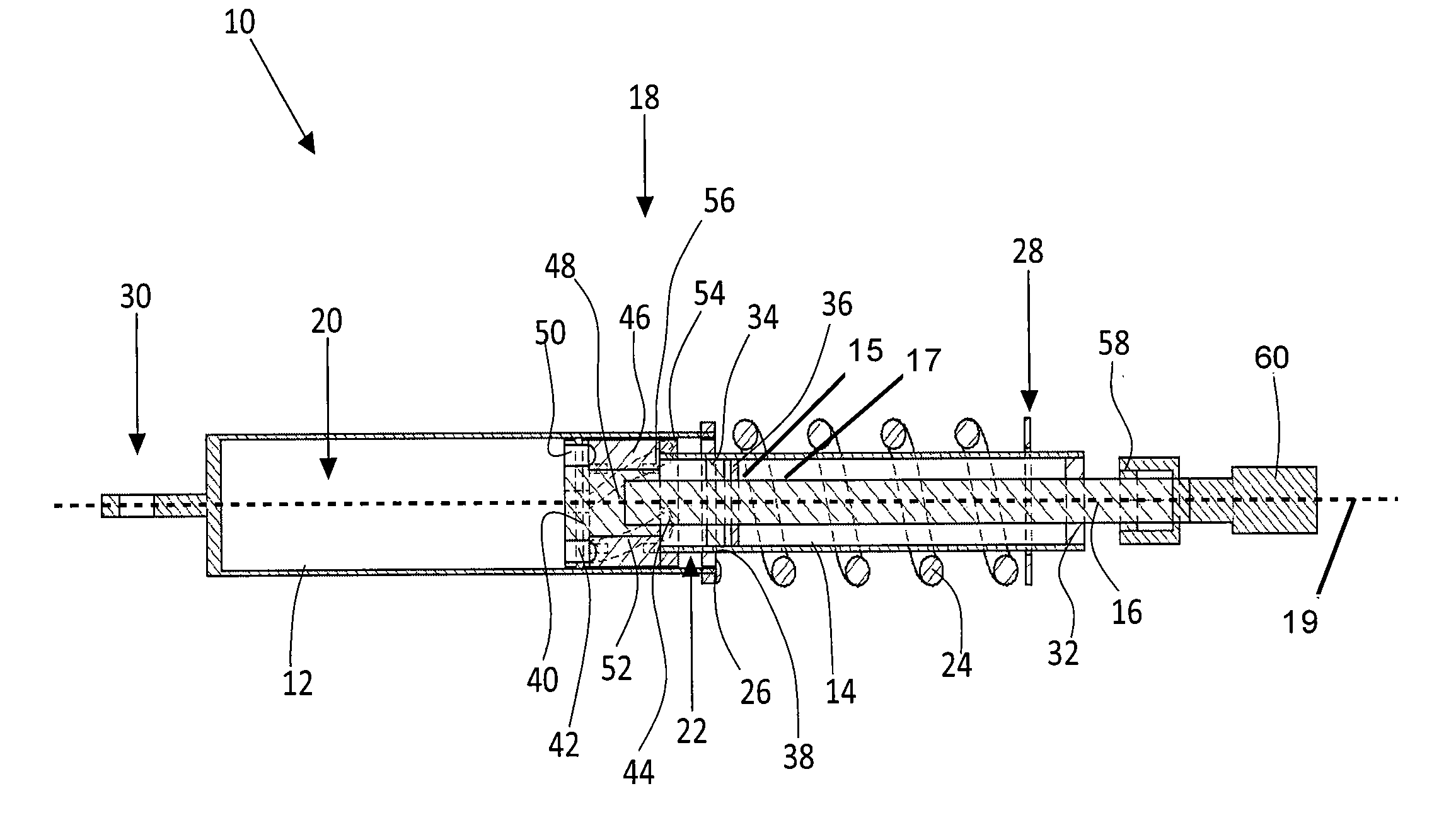
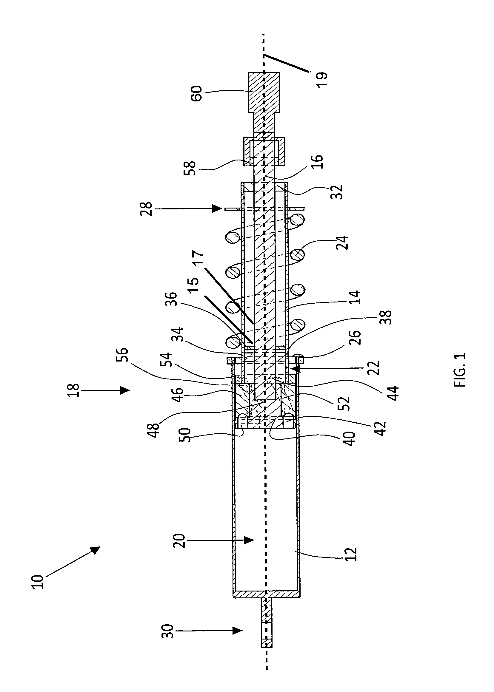
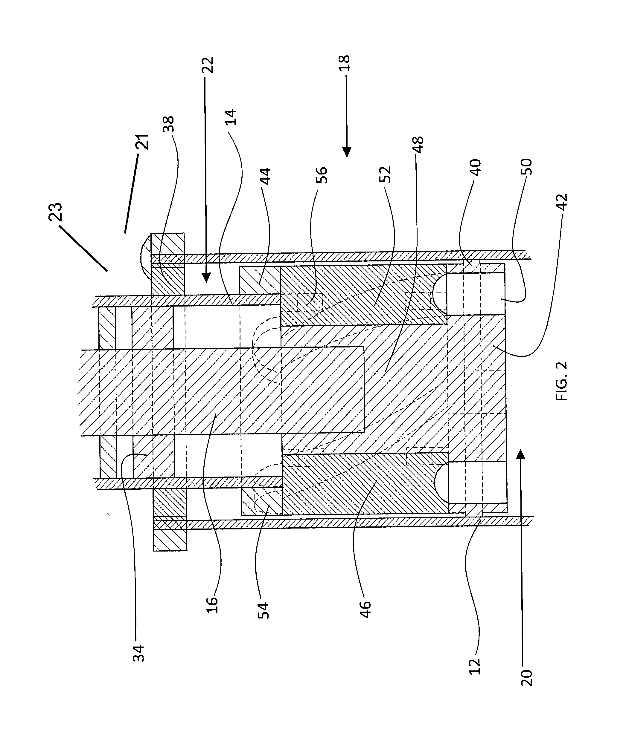
"The present invention provides a variable damping apparatus that combines fluid flow path restriction and variable Coulomb damping in order to control the overall damping force of a semi-active damping apparatus. The apparatus includes an elastically deformable elastomer member that is sandwiched between upper and lower piston mounts and is controlled by an actuated deformation mechanism. The elastomer member contains internal fluid channels that align with the piston mounts to induce Coulomb friction and increase the damping force. The apparatus can vary the damping force levels between high and low settings by manipulating the position of the lower piston mount. The invention provides a more effective and precise means to control the damping force in a semi-active damping apparatus."

Problems solved by technology

Furthermore, the available volume by which fluid passes along the outer walls of the elastomer member is capable of being greatly reduced as it expands outward, again resulting in an increase in fluid flow restriction.
Furthermore, when the elastomer is greatly compressed, as in a driving scenario where the highest available damping forces are required, the outer wall of the elastomer is able to make physical contact with the inner wall of the shock tube, thereby inducing a large amount of Coulomb friction, and greatly increasing the damping force.

Method used


Image

  • Variable-Elastomer Semi-Active Damping Apparatus
  • Variable-Elastomer Semi-Active Damping Apparatus
  • Variable-Elastomer Semi-Active Damping Apparatus

Examples


Embodiment Construction

[0020]The embodiments of the present invention described below are not intended to be exhaustive or to limit the invention to the precise forms disclosed in the following detailed description. Rather, the embodiments are chosen and described so that others skilled in the art may appreciate and understand the principles and practices of the present invention.

[0021]Unless defined otherwise, all technical and scientific terms used herein have the same meaning as commonly understood by one of ordinary skill in the art to which this invention belongs. Although any method and materials similar or equivalent to those described herein can be used in the practice or testing of the present invention, the specific methods and materials are now described.

[0022]All references mentioned hereunder are incorporated by reference in their entirety. Unless mentioned otherwise, the techniques employed or contemplated herein are standard methodologies well known to one of ordinary skill in the art and t...


PUM


Abstract

A variable semi-active damping assembly comprising a shock body defining a fluid-filled chamber; a piston tube having a first end slidably disposed within the shock body; an inner rod slidably disposed within the piston tube and the shock body, the inner rod having a first end connected to a lower piston mount and a second end extending outward from the piston tube and engaging an adjustment mechanism that is configured to move the inner rod with respect to the shock body; an upper piston mount slidably disposed within the shock body and connected to the piston tube; and a deformable member disposed between the lower piston mount and the upper piston mount, the deformable member being configured to transition between a compressed state and a non-compressed state in response to movement by the lower piston mount.

Description

TECHNICAL FIELD[0001]The present invention generally relates to active, semi-active, adaptive, or variable vibration damping systems and more particularly to apparatuses and methods for managing the transmission of vibratory and impact forces between two interconnected components that move relative to one another.BACKGROUND OF THE INVENTION[0002]Conventional dampers, or shock absorbers, used in automotive and other vehicular suspension systems, provide passive vibration control with a constant damping coefficient. To achieve a passive damping force that accentuates the comfort of the vehicle's ride as opposed to its handling dynamics, a low damping force or “soft” setting is used. By contrast, to achieve a high damping force that accentuates the handling dynamics of the vehicle as opposed to its ride comfort, a high damping force or “hard” setting is used. The conventional design of dampers used to achieve these various handling characteristics generally include an outer cylinder or...

Claims


Application Information

Patent Timeline
Patent Type & Authority Applications(United States)
IPC IPC(8): B60G15/06B60G17/08
CPCB60G17/08B60G2202/24F16F9/3214F16F9/3415F16F9/3405
Inventor RODENBECK, PHILLIP D.
Owner RODENBECK PHILLIP D
Learn More