A rotary detonation combustor

A combustion chamber and detonation technology, which is applied in the field of combustion chambers, can solve the problems that detonation waves are easy to degrade and disappear, detonation waves are only formed at the head of the combustion chamber, and fuel filling space is insufficient, so as to shorten the transition from slow combustion to detonation combustion distance, improve fuel filling efficiency, and improve the effect of overall self-pressurization capability

Inactive Publication Date: 2015-12-09
XIAN THERMAL POWER RES INST CO LTD
View PDF9 Cites 6 Cited by
  • Summary
  • Abstract
  • Description
  • Claims
  • Application Information

AI Technical Summary

Problems solved by technology

[0005] The purpose of the present invention is to solve the problems existing in the existing rotary detonation combustion chamber that the detonation wave is only formed at the head of the combustion chamber, the fuel filling space is insufficient, and the detonation wave is easy to degrade and disappear, and provides a rotary detonation combustion chamber

Method used


Image

  • A rotary detonation combustor
  • A rotary detonation combustor
  • A rotary detonation combustor

Examples


Embodiment

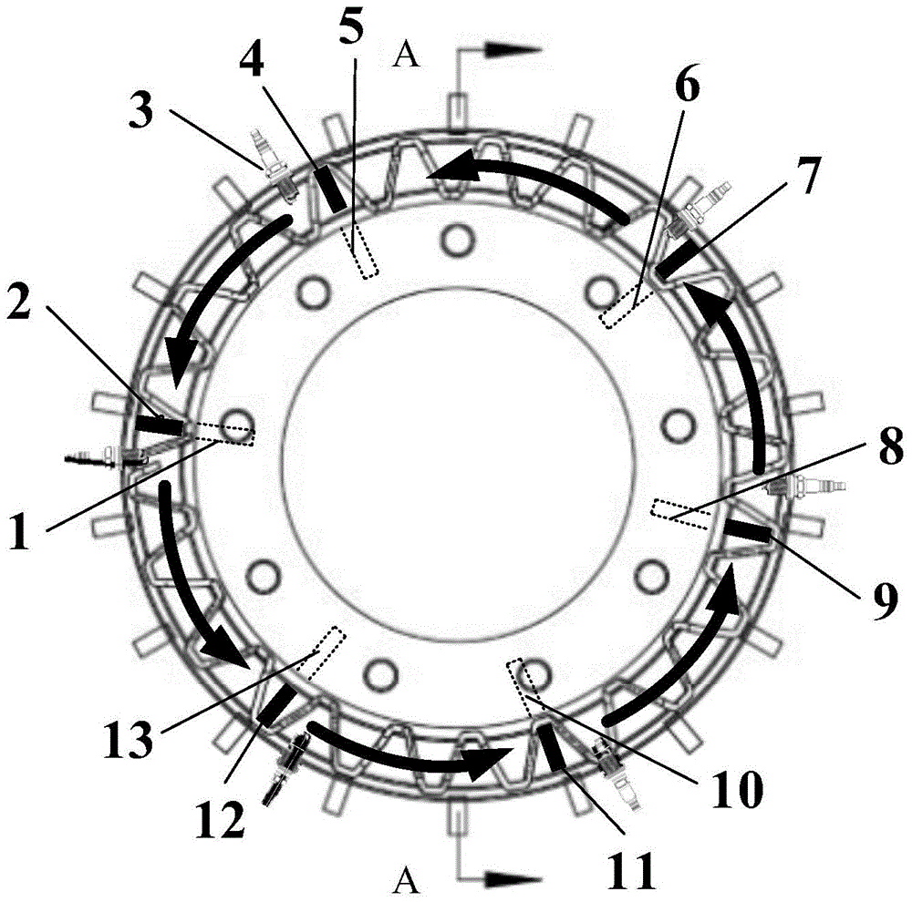
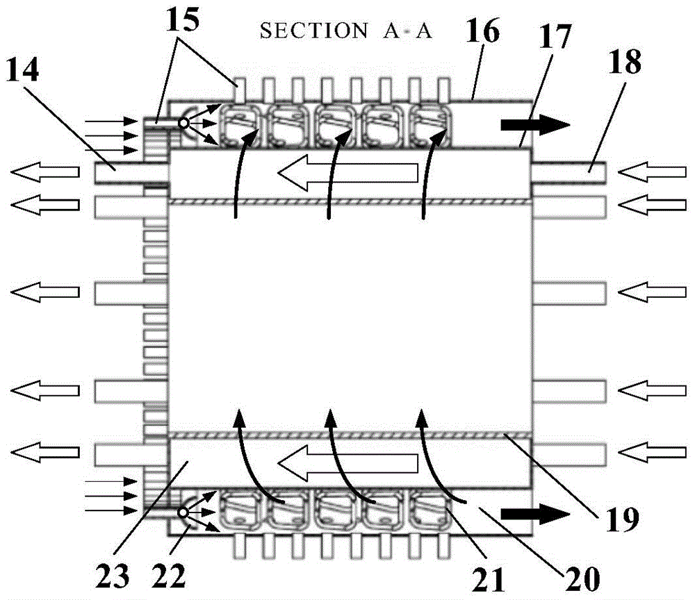
[0031] see figure 1 and figure 2 , a rotary detonation combustion chamber of the present invention, comprising a detonation combustion chamber 20, a fuel preheating chamber 23, a fuel nozzle 15, a spiral obstacle 21, a pre-detonation pressure wave attenuation structure 22, a fuel inlet pipeline 18, a fuel Outlet line 14 and spark plug 3. In this embodiment, the detonation combustion chamber 20 and the fuel preheating chamber 23 are coaxially arranged; the detonation combustion chamber has an outer diameter of 1400 mm, an inner diameter of 1200 mm, and a length of 1100 mm; an outer diameter of the fuel preheating chamber of 1190 mm, an inner diameter of 890 mm, and a length of 1100 mm. The pre-detonation pressure wave attenuation structure 22 is arranged at the head of the detonation combustion chamber 20, and is fixedly connected to the detonation combustion chamber 20 through the fuel nozzle 15. The detonation pre-detonation pressure wave attenuation structure 22 is a semic...


PUM


Abstract

The invention provides a rotating detonation combustion chamber. According to the rotating detonation combustion chamber, besides a plurality of fuel spray nozzles which are distributed on the head portion of the combustion chamber in an annular mode at equal intervals, a plurality of fuel spray nozzles are further evenly arranged in the axial direction and the circumferential direction of an outer shell of the combustion chamber, so that the annular detonation combustion chamber is divided into a plurality of small spaces; each spray nozzle is responsible for supplying fuel to the corresponding small space, and therefore filling efficiency of fuel can be improved, the filling space of fuel of the combustion chamber can be enlarged, and the combustion thermal intensity of the combustion chamber can be improved. The axial distance of rotating detonation combustion waves can be lengthened due to the fact that the filling space of fuel of the combustion chamber is enlarged, so that the rotating detonation waves penetrate through the whole combustion chamber, and meanwhile the rotating detonation waves can be prevented from degeneration and disappear which are caused by fuel shortage in the spreading process. A spiral obstacle is arranged in an annular cavity of the rotating detonation combustion chamber in the circumferential direction, and therefore the distance by which slow combustion is converted into detonation combustion in the starting process of the combustion chamber can be shortened, the intensity of the rotating detonation waves is enhanced, the overall self-pressurization capacity is improved in the combustion process of the combustion chamber, and meanwhile stability of the rotating detonation waves can be enhanced in the spreading process.

Description

【Technical field】 [0001] The invention relates to a combustion chamber of a gas turbine, in particular to a rotating detonation combustion chamber, which is used for power generation and power equipment of the gas turbine. 【Background technique】 [0002] Slow combustion and detonation combustion are the two main combustion modes for fuel energy release. Slow combustion combustion is to transfer heat to the unburned mixture through heat conduction, thermal diffusion and thermal radiation, heat and burn layer by layer, and then realize the propagation of slow combustion waves. The propagation speed of slow combustion wave is relatively low, generally about several meters to tens of meters per second. The detonation combustion is realized by the strong impact and compression of the detonable mixture layer by layer by the shock wave, causing a high-speed chemical reaction. It can be considered that the detonation combustion wave is a strong shock wave coupled with chemical reac...

Claims


Application Information

Patent Timeline
Patent Type & Authority Patents(China)
IPC IPC(8): F23R3/52F23R3/28
Inventor 李晓丰肖俊峰王玮于飞龙
Owner XIAN THERMAL POWER RES INST CO LTD
Why Eureka
Try Eureka