Combination mounting ring

a mounting ring and combination technology, applied in the direction of shafts, bearings, rod connections, etc., can solve the problems of increasing the annular space between the housing and the outer part, excessive wear between the balls of the bearing and the race, and reducing the nvh (noise, vibration and harshness) performance, so as to achieve the effect of reducing the axial distan

Active Publication Date: 2008-03-13
SAINT GOBAIN PERFORMANCE PLASTICS RENCOL
View PDF16 Cites 6 Cited by
  • Summary
  • Abstract
  • Description
  • Claims
  • Application Information

AI Technical Summary

Benefits of technology

[0066]wherein the shaft applies an axial force against the annular part of the combination mounting ring such as to reduce the axial distance between the first and second parts of the annular part and press the annular part into contact with the body; and
[0067]wherein the first mating component contacts and applies a radial force against the projections of the cylindrical part of the combination mounting ring such as to compress the projections and press the cylindrical part into contact with the second mating component, thereby to secure together the shaft and the housing.

Problems solved by technology

A problem with known assemblies of a bearing, housing and tolerance ring, such as in the electric motor of FIG. 2, is that, if the assembly gets hot, the housing may expand thereby increasing the annular space between the housing and the outer part of the bearing.
When this happens, the bearing may be permitted to move axially relative to the housing, and the races of the bearing may be permitted to move axially relative to each other (i.e. rattle), which can lead to excessive wear between the balls of the bearing and the races, and also reduced NVH (noise, vibration and harshness) performance.
While tolerance rings and wavy washers have many beneficial attributes, they can be time-consuming and awkward to fit in an assembly.

Method used


Image

  • Combination mounting ring
  • Combination mounting ring
  • Combination mounting ring

Examples


first embodiment

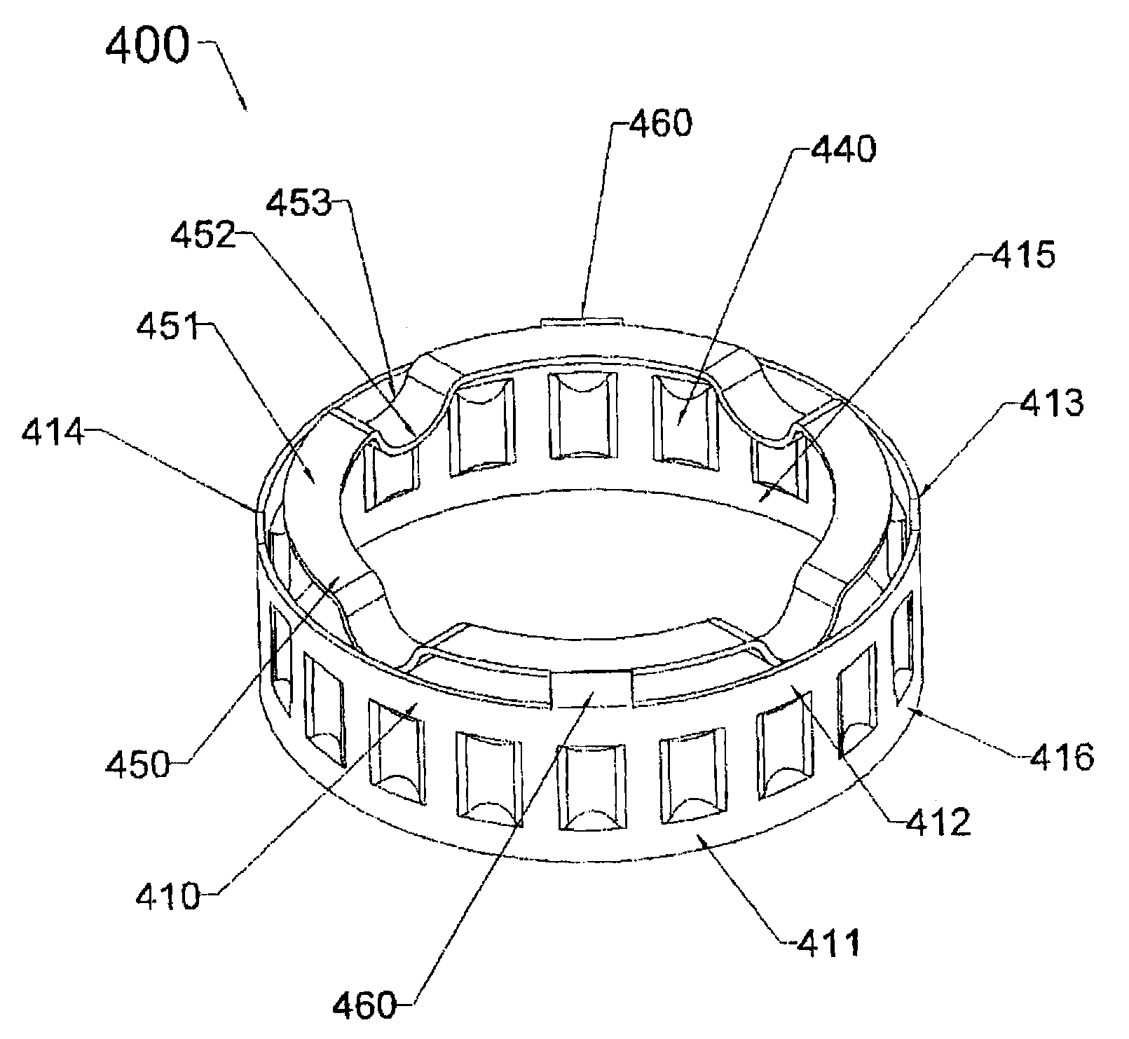
[0091]FIG. 4 shows a combination mounting ring 400 of spring steel according to the present invention. The combination mounting ring 400 includes a hollow cylindrical part 410 with a series of projections 440 extending radially inwards from the inner surface thereof. In other embodiments, these projections may extend radially outwards from the external surface of the cylindrical part 410. The cylindrical part 410 has the general form of a band and the series of projections 440 is axially flanked by annular regions 411 and 412 of the cylindrical part 410 that have no formations.

[0092]The cylindrical part 410 has two axially extending discontinuities 413, 414 in its circumference, such that the cylindrical part 410 in fact comprises two continuous portions 415, 416 separated by the gaps 413, 414. Each portion 415, 416 has nine projections 440 extending from it. The projections 440 of each portion 415, 416 are equally spaced, but the spaces between adjacent projections 440 on either si...

second embodiment

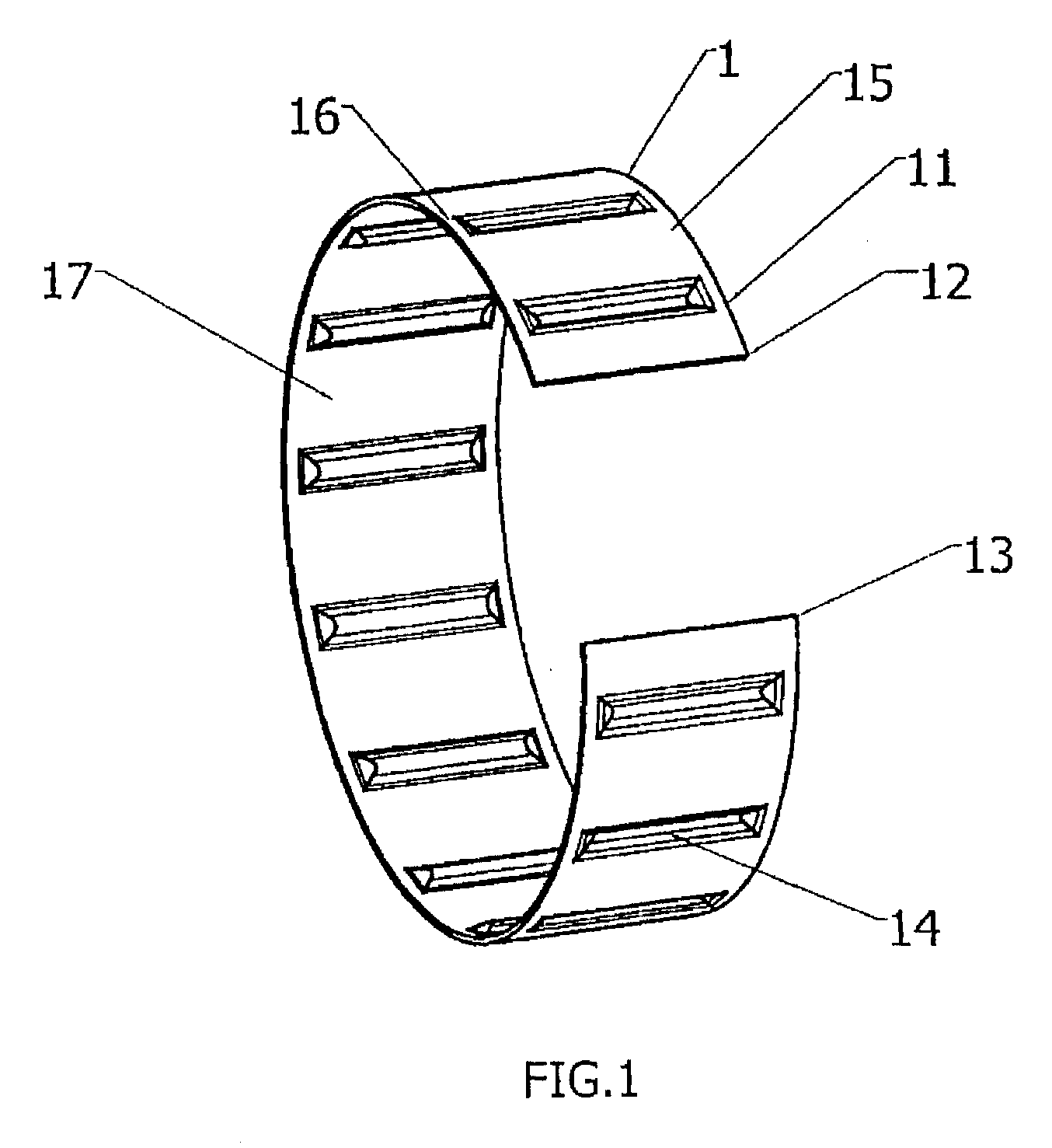
[0101]FIG. 6 shows a combination mounting ring 200 having a resilient cylindrical band 202 formed e.g. by bending a strip of spring steel. An axial split 204 occurs in the circumference of the band 202. This permits the band 202 to open or close to be retained on or in a inner or outer component. For example, the split 204 may be closed to allow the band 202 to be placed inside a bore in a housing (not shown). On release, the resilience of the band 202 causes the split to open again, whereby the band 202 is retained against the surface of the bore. Although the split 204 is open in this embodiment, it is possible for it to be closed, i.e. for the circumferential ends of the band to overlap.

[0102]A plurality of projections 206 extend radially inwards from the band 202. Each projection is a rounded ridge 206, e.g. formed by stamping the band 202 before it is bent into its cylindrical configuration.

[0103]Four axial spring elements 208 are attached via tabs 210 to four separate location...


PUM


Abstract

A combination mounting ring of resilient material, for connecting a shaft within a bore of a housing, has a hollow cylindrical part having radially extending projections. This part is for locating between the outer surface of the shaft and the inner surface of the bore, the radially extending projections being under compression and thus securing the shaft within the bore. The combination mounting ring further has an axial spring element extending radially inward from the cylindrical part and having two portions at different axial positions. The axial spring element is for locating between the shaft and a body axially displaced from the shaft, and serves to minimize axial movement of the shaft within the bore of the housing. The axial spring element may either be an annular part or a tab extending from an axial edge of the cylindrical part.

Description

FIELD OF THE INVENTION[0001]1. Background of the Invention[0002]The present invention relates to a mounting ring. It also relates to an assembly having a housing with a bore therein and a shaft or bearing (hereinafter the term “shaft” encompasses a bearing) received in the bore and connected thereto to be held in the bore by such a mounting ring.[0003]2. Description of the Prior Art[0004]It is known to connect together a housing and a shaft received in a bore of the housing by a mounting ring in the form of a tolerance ring. The tolerance ring may be used to hold the shaft in place in the bore, or it may act as a force limiter to permit torque to be transmitted between the shaft and the housing. Tolerance rings are used, for example, to transmit torque, provided that torque does not exceed some predetermined value. The use of a tolerance ring permits minor variations in the diameter of the shaft and the bore to be accommodated without affecting the housing and shaft interconnection....

Claims


Application Information

Patent Timeline
Patent Type & Authority Applications(United States)
IPC IPC(8): F16D3/04
CPCF16B21/20F16B43/00F16C25/08Y10T403/7061F16C35/077F16F1/025F16C27/04F16C25/083F16C2380/26
Inventor SNADDEN, ANTONYBAKER, MARCUS
Owner SAINT GOBAIN PERFORMANCE PLASTICS RENCOL
Why Eureka
Try Eureka