Highly efficient fixed gap bicycle axel skewer and method of use

Inactive Publication Date: 2012-10-18
ASHMAN J LEONARD
View PDF10 Cites 8 Cited by
  • Summary
  • Abstract
  • Description
  • Claims
  • Application Information

AI Technical Summary

Benefits of technology

[0012]The third embodiment of the present invention again uses a simple shear force differential. The shear force between the external threads of the insert and the internal threads of the captive nut is greater than the shear force between the threads of the skewer rod and the internal threads of the insert in the same way as in the first embodiment, however in the third embodiment the shear force differenti

Problems solved by technology

Once the wheel is in the correct position in the lugs of the bicycle frame the lever is operated which results in a clamping force to fix the wheel in place.
While these method

Method used


Image

  • Highly efficient fixed gap bicycle axel skewer and method of use
  • Highly efficient fixed gap bicycle axel skewer and method of use
  • Highly efficient fixed gap bicycle axel skewer and method of use

Examples


first embodiment

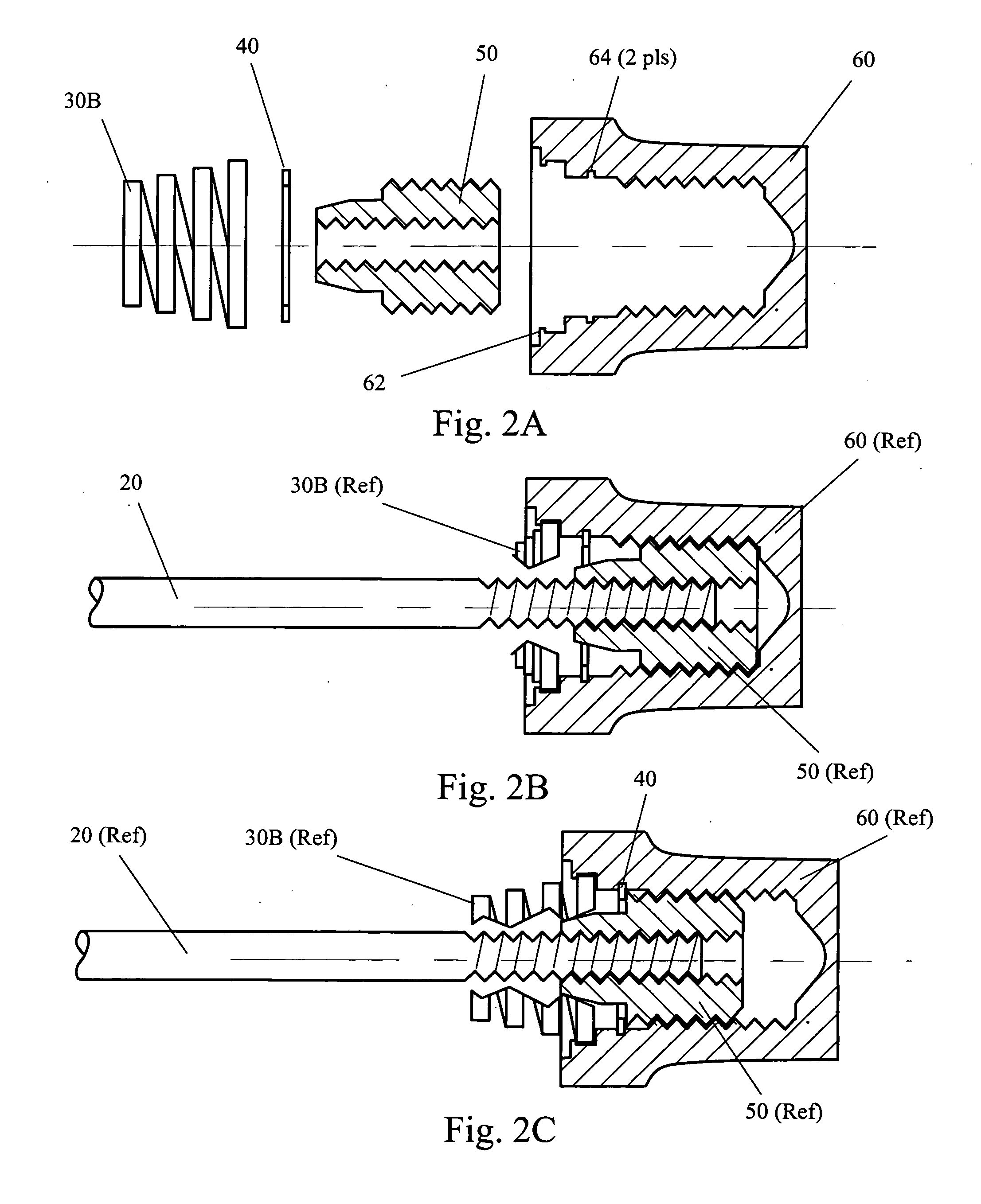
[0021]Turning now to FIG. 2, several views of the details of the present invention are shown. Note that while FIG. 2, as well as FIGS. 3, 4, and 5, discuss the details of the present invention with respect to a driven, or rear wheel, the apparatus is suitable for both driven and non-driven wheels, thus may be used for both front and rear wheel applications.

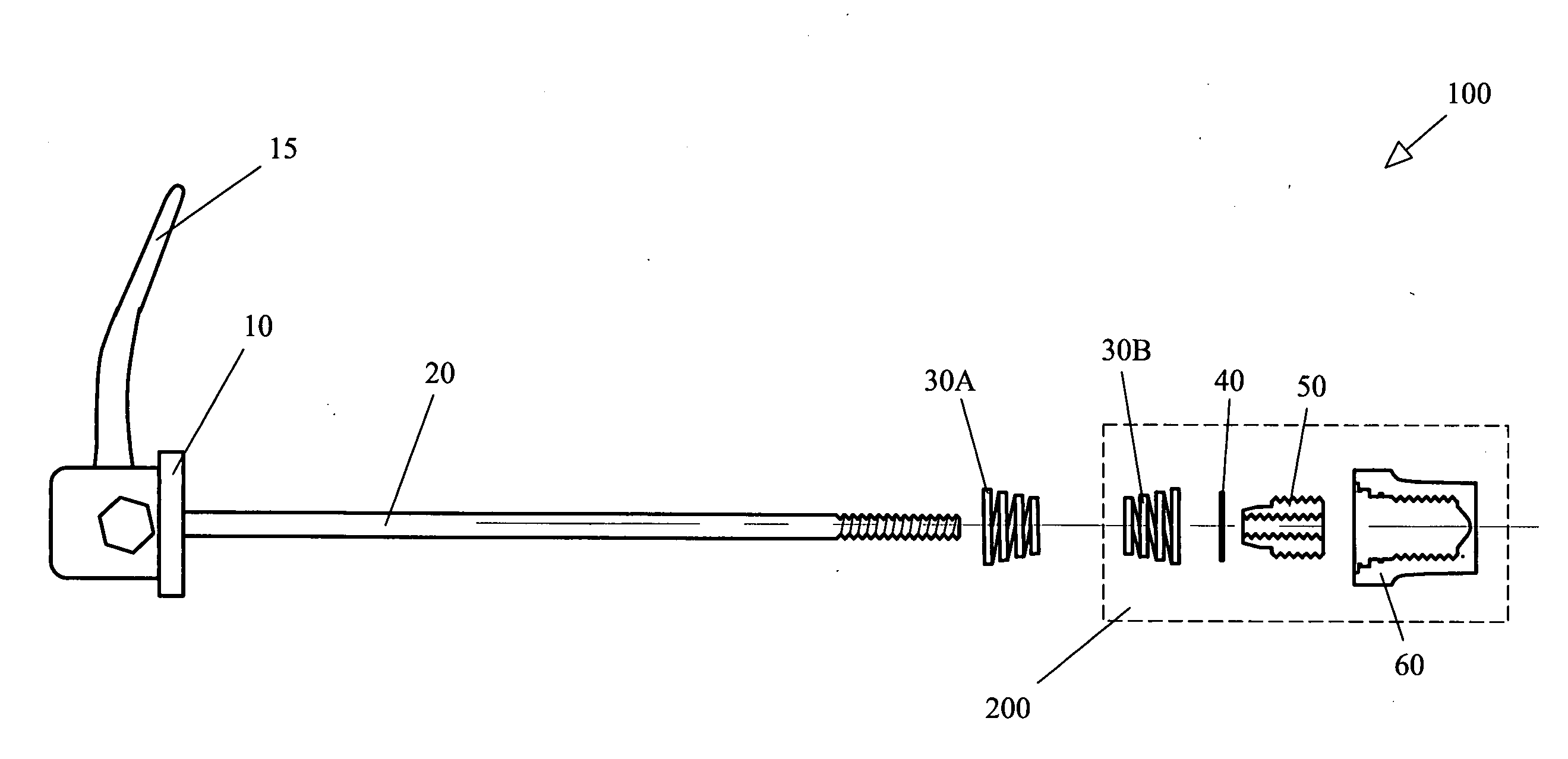
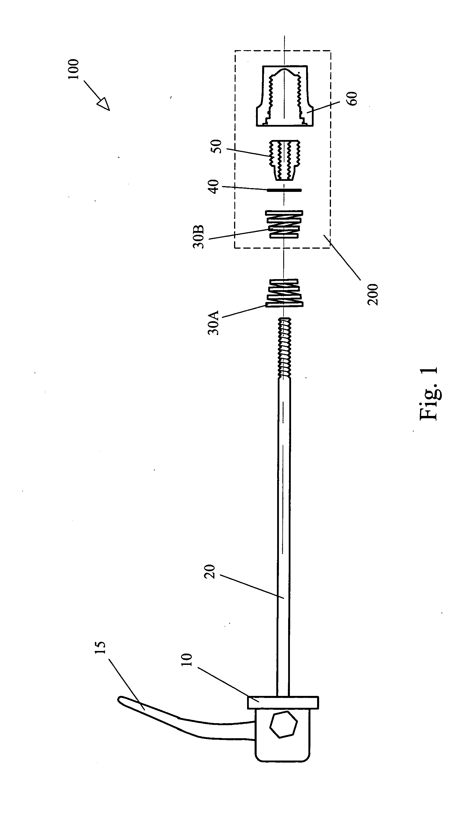
[0022]Beginning with FIG. 2A, an exploded / sectioned view of the captive nut assembly 200 is shown including captive nut 60, insert 50, stop ring 40 and spring 30B. The outer threads of insert 50 mate with the internal threads of captive nut 60 such that the fit is not tight. As explained further below, this is so that when the rider turns the skewer rod 20, the insert 50 turns with respect to the captive nut 60 while remaining stationary to the insert 50. Stop ring 40 is of the c-ring type and snaps into slots 64 such that when the skewer rod / insert combination is turned, no lateral movement beyond stop ring 40 is permitted. Alter...

second embodiment

[0025]Referring now to FIG. 3, several views of the details of the present invention are shown. Beginning with FIG. 3A, an exploded / sectioned view of the captive nut 60, set screw 70, insert 50, stop ring 40 and spring 30B is shown. The outer threads of insert 50 mate with the internal threads of captive nut 60 such that the fit is not tight. As explained further below, this is so that when the rider turns the skewer rod 20, the insert 50 turns with respect to the captive nut 60 while remaining stationary to the insert 50. Stop ring 40 snaps into slots 64 such that when the skewer rod / insert combination is turned, no lateral movement beyond stop ring 40 is permitted.

[0026]Spring 30B snaps into place over lip 62 such that when lateral movement of the skewer rod 20 occurs, the spring 30B travels with captive nut 60. In this way, when the wheel is removed from the chain stay lugs the spring remains with the captive nut 60.

[0027]Hole 66 is provided in the end of captive nut 60 to allow ...

third embodiment

[0030]Looking now to FIG. 4, several views of the details of a third, preferred embodiment of the present invention are shown. Beginning with FIG. 4A, an exploded / sectioned view of the captive nut 60, insert 50, stop ring 40 and spring 30B is shown. In this third embodiment, the insert 50 is further comprised of outer sleeve 54 and inner barrel 52. Outer sleeve 54 is made of the same material as captive nut 60, typically aluminum. Inner barrel 52 is made of a material such as neoprene. Inner barrel 52 is force fit into outer sleeve 54, together forming insert 50.

[0031]The outer threads of insert 50 mate with the internal threads of captive nut 60 such that the fit is not tight. As explained further below, this is so that when the rider turns the skewer rod 20, the insert 50 turns with respect to the captive nut 60 while remaining stationary to the insert 50. Stop ring 40 snaps into slots 64 such that when the skewer rod / insert combination is turned, no lateral movement beyond stop r...


PUM


Abstract

The present invention teaches an apparatus and method of use for a highly efficient bicycle skewer. In each of three separate embodiments an insert moves laterally with respect to a captive nut in such a way as to provide the necessary clearance required to remove a wheel or attach a wheel to a bicycle frame. The apparatus is constructed in such a way as to allow the removal and attachment without the need for adjustment of the skewer as is required by the prior art devices and is suitable for both front and rear wheels.

Description

BRIEF DESCRIPTION[0001]The subject of this invention relates to the bicycle industry. More specifically, the disclosed invention teaches a novel bicycle axel skewer that once set, maintains the proper gap between the skewer and mounting lugs of a bicycle frame thereby improving the user's ability to maintain the bicycle. The apparatus of the disclosed invention may be used for driven and non-driven hubs.BACKGROUND OF THE INVENTION[0002]Chain driven bicycle drive trains have existed for many years. Generally the chain receives power input from a peddle crank that has a motive force exerted upon it from a rider's legs. The force is transferred by the chain to the driven wheel by a geared cog, for example, which is in turn mechanically linked to a hub. The hub is attached to the drive wheel by means of spokes or solid inserts such as in the so-called disk wheels. In this way linear force from a rider's legs is transformed to rotational force applied to the wheel and then to the road su...

Claims


Application Information

Patent Timeline
IPC IPC(8): B60B35/04
CPCB60B27/026B60B2900/531B60B2900/3314B60B31/00
Inventor ASHMAN, J. LEONARD
Owner ASHMAN J LEONARD
Why Eureka
Try Eureka