Light emitting element drive device and mobile apparatus

a technology of driving device and light emitting element, which is applied in the direction of instruments, television systems, optics, etc., can solve the problem of inability to achieve imaging at desired timing

Inactive Publication Date: 2012-10-18
PANASONIC INTELLECTUAL PROPERTY MANAGEMENT CO LTD
View PDF23 Cites 10 Cited by
  • Summary
  • Abstract
  • Description
  • Claims
  • Application Information

AI Technical Summary

Benefits of technology

[0024]With such a configuration, in the first discharging state in which the electric power stored in the first electricity storage element is supplied to the light emitting element, the drive unit series-connects the battery power supply, the first electricity storage element, and the light emitting element. Herewith, as a result that the added voltage value of electric power suppliable from the battery power supply and the first electricity storage element to the light emitting element is set higher than a voltage at which the light emitting element emits light, discharg...

Problems solved by technology

Thus, in a case where short-interval (continuous) light emission (i.e. imaging) is required, electricity sto...

Method used


Image

  • Light emitting element drive device and mobile apparatus
  • Light emitting element drive device and mobile apparatus
  • Light emitting element drive device and mobile apparatus

Examples


first exemplary embodiment

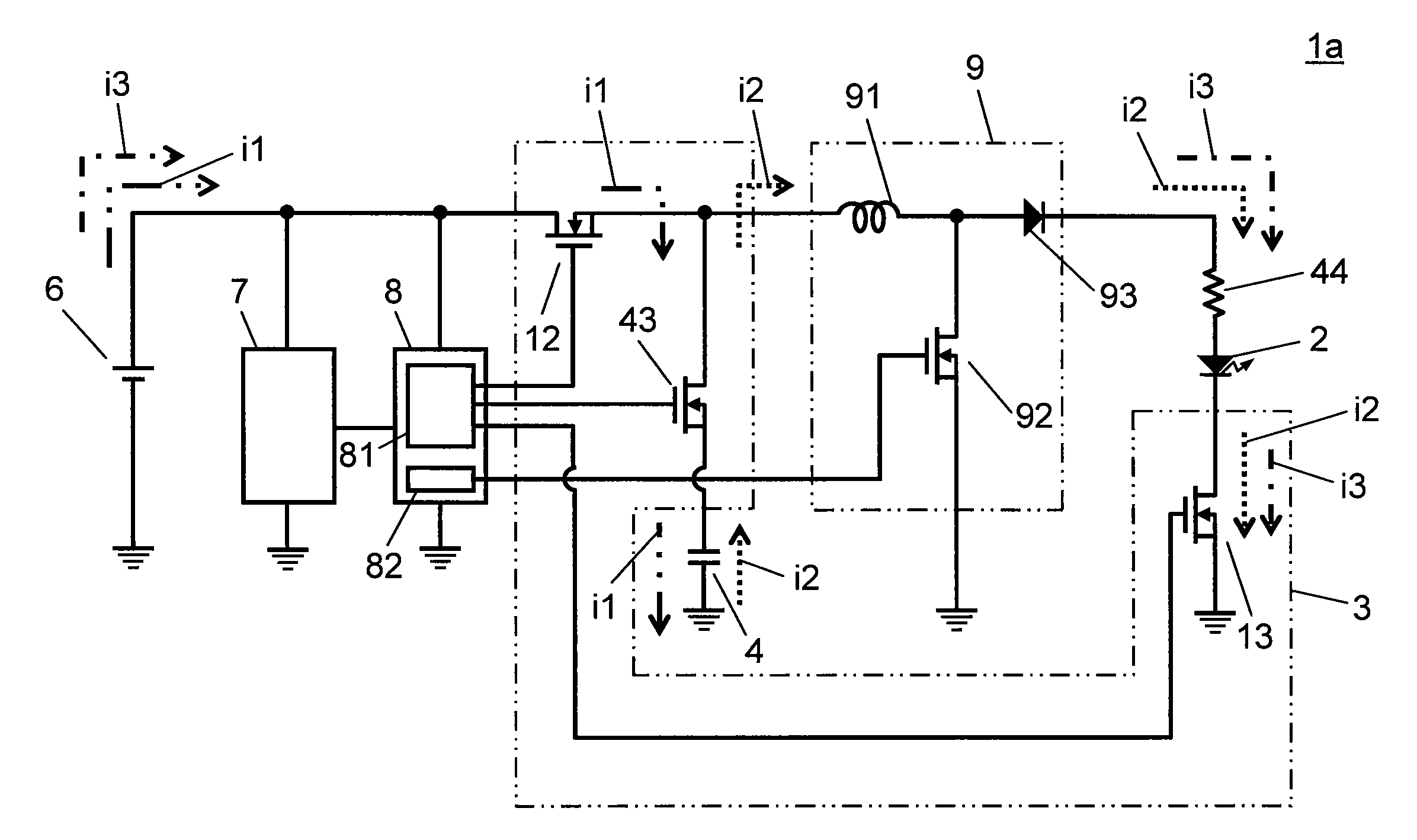
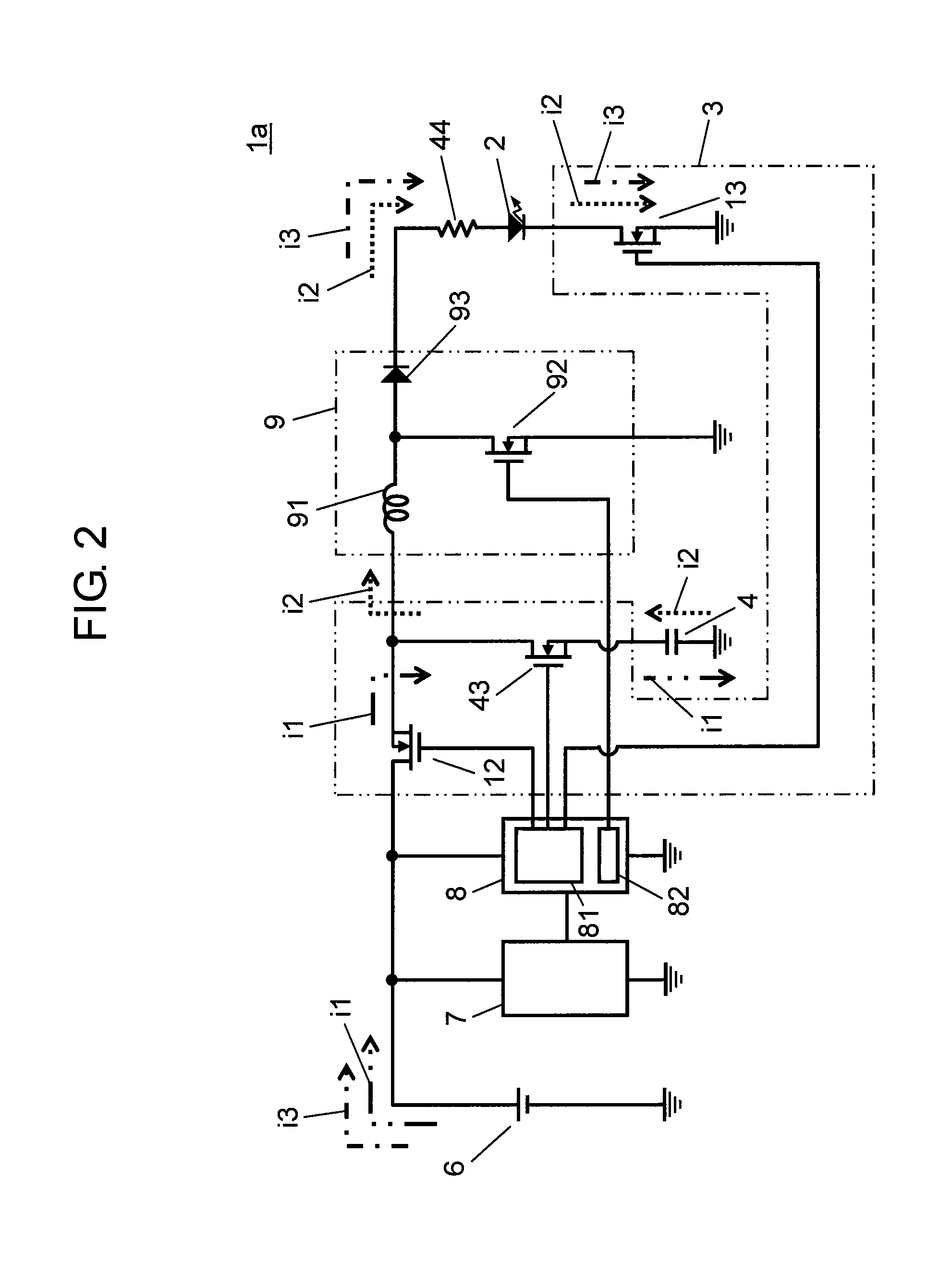
[0041]Hereinafter, a description is made of a light emitting element drive device and a mobile apparatus according to a first exemplary embodiment of the present invention in reference to FIGS. 1A through 3. In FIGS. 1A through 3, a component or element with the reference mark same as that of FIG. 13 is the same as that of the conventional technology, unless particularly described.

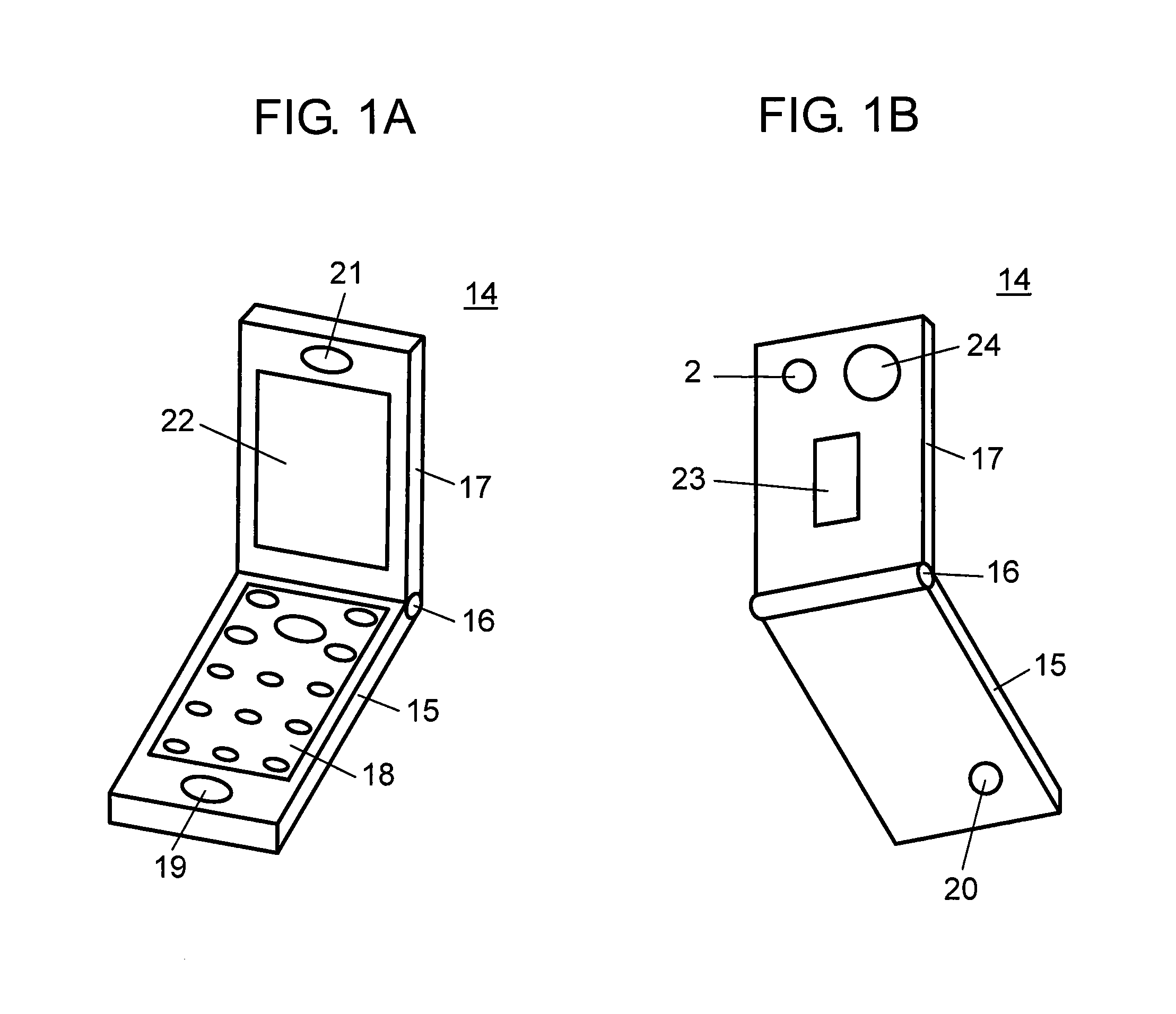
[0042]As shown in FIGS. 1A and 1B, mobile apparatus 14 according to the embodiment, with light emitting element drive device 1a provided, is a mobile phone incorporating an LED flash function and a digital camera function. Further, mobile apparatus (hereinafter also referred to as a mobile phone) 14 includes first body 15; and second body 17 foldable first body 15 through hinge mechanism 16.

[0043]First body 15 includes operation key unit 18 composed of such as numeric keys, on the inner surface of mobile phone 14 (in a folded state), for receiving input for operating mobile phone 14; and microphone 19 for ...

second exemplary embodiment

[0066]Next, a description is made of a light emitting element drive device according to the second exemplary embodiment of the present invention in reference to FIGS. 6 through 8. In FIGS. 6 through 8, a component or element with the reference mark same as that of FIG. 14 is the same as that of the conventional technology, unless particularly described.

[0067]Light emitting element drive device 1b includes (besides light emitting element 2) drive unit 3 for light emitting element 2; first and second electricity storage elements 4 and 5 capable of storing electric power; and battery power supply 6 capable of supplying electric power to drive unit 3 and each electricity storage elements 4 and 5. Light emitting element drive device 1b further includes camera unit 7 capable of imaging, having an imaging element (not shown) for receiving the light collected by optical system 24 (refer to FIG. 1B); and control unit (CPU) 8 for controlling the entire device including drive unit 3.

[0068]Ligh...

third exemplary embodiment

[0082]Next, a description is made of a light emitting element drive device according to the third exemplary embodiment of the present invention in reference to FIGS. 9 through 12. In FIGS. 9 through 12, a component or element with the reference mark same as that of FIGS. 6 to 8 is the same as that of the second exemplary embodiment, unless particularly described. A mobile apparatus incorporating light emitting element drive device 1c is configured in the same way as mobile phone 14 described in the first exemplary embodiment, and thus its description is omitted.

[0083]As shown in FIG. 9, light emitting element drive device 1c according to this exemplary embodiment is different from light emitting element drive device 1b according to the second exemplary embodiment in the configuration of drive unit 3. In this exemplary embodiment, drive unit 3 includes first and second inverters (NOT gate) 33 and 34, first and second AND gates 35 and 36, and first through sixth switch units (CMOS) 37...


PUM


Abstract

A light emitting element drive device of the present invention includes a light emitting element; a drive unit for driving the light emitting element; an electricity storage element capable of storing electric power; a battery power supply capable of supplying electric power to the electricity storage element; and a boost chopper circuit having an inductor, for boosting voltage by opening and closing a switching element. The drive unit is switchable between three states: a storing state in which electric power from the battery power supply is stored in the electricity storage element; a first discharging state in which the electric power stored in the electricity storage element is supplied to the light emitting element; and a second discharging state in which electric power from the battery power supply is boosted by the boost chopper circuit and is supplied to the light emitting element.

Description

TECHNICAL FIELD[0001]The present invention relates to a light emitting element drive device including a light emitting element, a drive unit for driving the light emitting element, an electricity storage element capable of storing electric power, and a battery power supply capable of supplying electric power to the drive unit and the electricity storage element; and to a mobile apparatus including the drive device.BACKGROUND ART[0002]As shown in FIG. 13, conventional light emitting element drive device 1d is known including light emitting element 2, drive unit 3 for driving light emitting element 2, electricity storage element 4 capable of storing electric power, battery power supply 6 capable of supplying electric power to electricity storage element 4, and boost chopper circuit 9 having inductor 91, for boosting voltage by opening and closing switching element 92. Boost chopper circuit 9 includes diode 93.[0003]Light emitting element drive device 1d further includes camera unit 7 ...

Claims


Application Information

Patent Timeline
IPC IPC(8): H05B37/02H05B44/00
CPCG03B15/0447G03B15/05Y02B20/346H04N5/23241H05B33/0818H04M1/22G03B2215/0503Y02B20/30H05B45/38H04N23/67H04N23/651
Inventor SUMISAKI, KATSUSHITANIGUCHI, TOSHIHIKOYOSHINO, TSUNEMIAMARI, SATOSHI
Owner PANASONIC INTELLECTUAL PROPERTY MANAGEMENT CO LTD
Why Eureka
Try Eureka