Battery balancing circuit and balancing method thereof and battery activation method

a battery module and circuit technology, applied in the direction of charging equalisation circuit, transportation and packaging, battery module, etc., can solve the problems of battery module life reduction, inrush current generation, etc., to increase the life of the battery module and extend the usage li

Inactive Publication Date: 2012-10-18
TREND POWER TECH CHANGSHU INC
View PDF2 Cites 56 Cited by
  • Summary
  • Abstract
  • Description
  • Claims
  • Application Information

AI Technical Summary

Benefits of technology

[0010]Briefly, the battery balancing circuit and the method thereof of the present invention can prevent an electric device circuit and / or a battery module connected to the battery balancing circuit from being damaged by inrush current to thereby extend their usage life. Similarly, the battery module activation method can increase the life of a battery module as well.

Problems solved by technology

However, when a newly added battery module connects to the existing battery module / modules in parallel, inrush current could be generated due to the voltage difference between the newly added and existing battery modules and then inputted into a load such as the aforementioned electric device and / or any of the battery modules.
Such inrush current would damage the load and / or the battery module and thereby reduce the electric device's life and / or cause the battery module many problems.
Besides, once a battery module is kept fully-charged or unused for a long time, it could be affected by salinization, electrode plate corrosion and / or thermal runaway which lead to degradation or dead of the battery module.

Method used


Image

  • Battery balancing circuit and balancing method thereof and battery activation method
  • Battery balancing circuit and balancing method thereof and battery activation method
  • Battery balancing circuit and balancing method thereof and battery activation method

Examples


Embodiment Construction

[0015]In an embodiment, the present invention provides a battery balancing circuit to balance the voltages between a plurality of battery modules connected in parallel. In another embodiment, the present invention provides a battery balancing method which can be executed by the above-mentioned battery balancing circuit. In a further embodiment, the present invention provides a battery module activation method which can be carried out by the above-mentioned battery balancing circuit.

[0016][Embodiment of Battery Balancing Circuit]

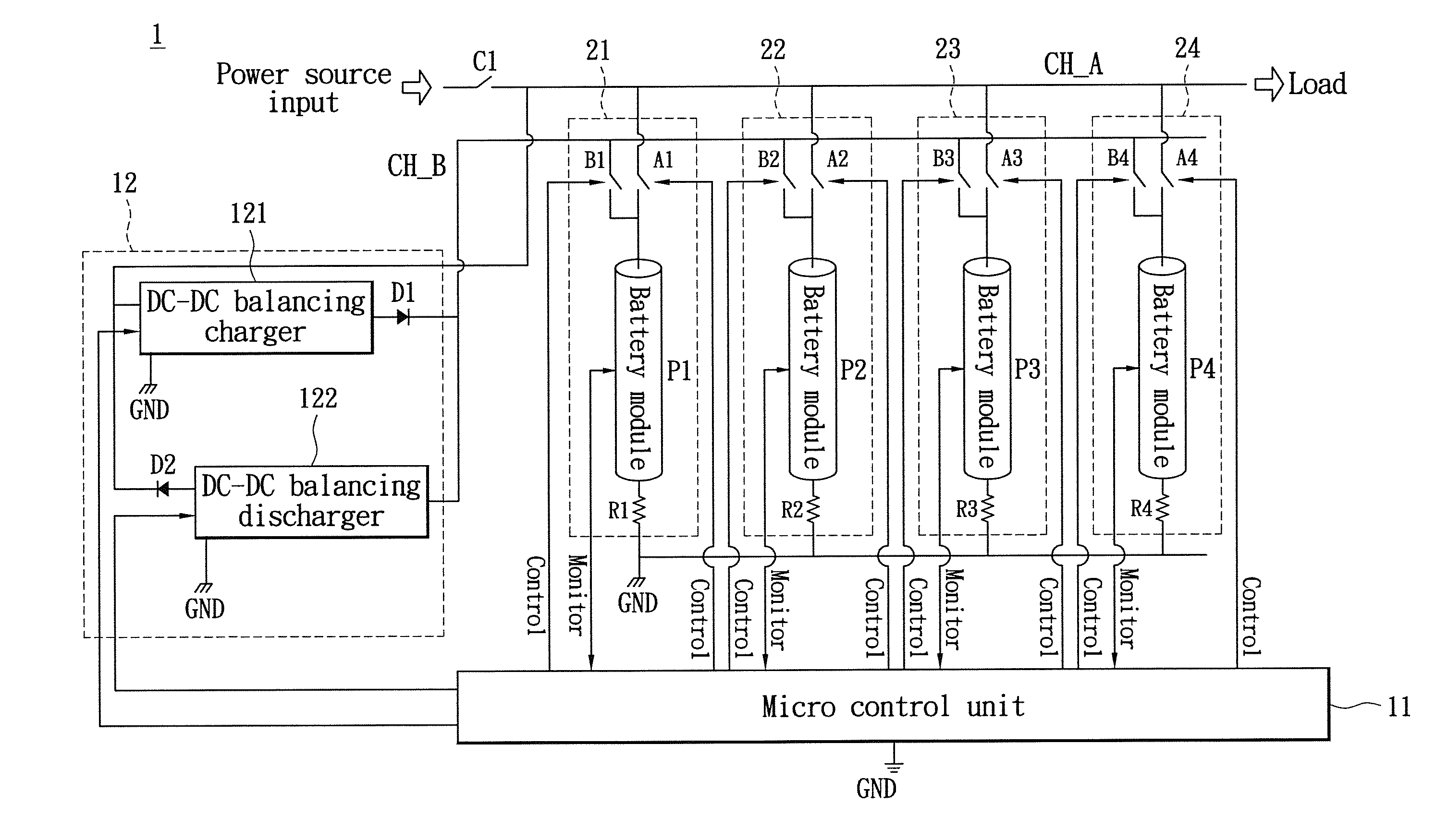
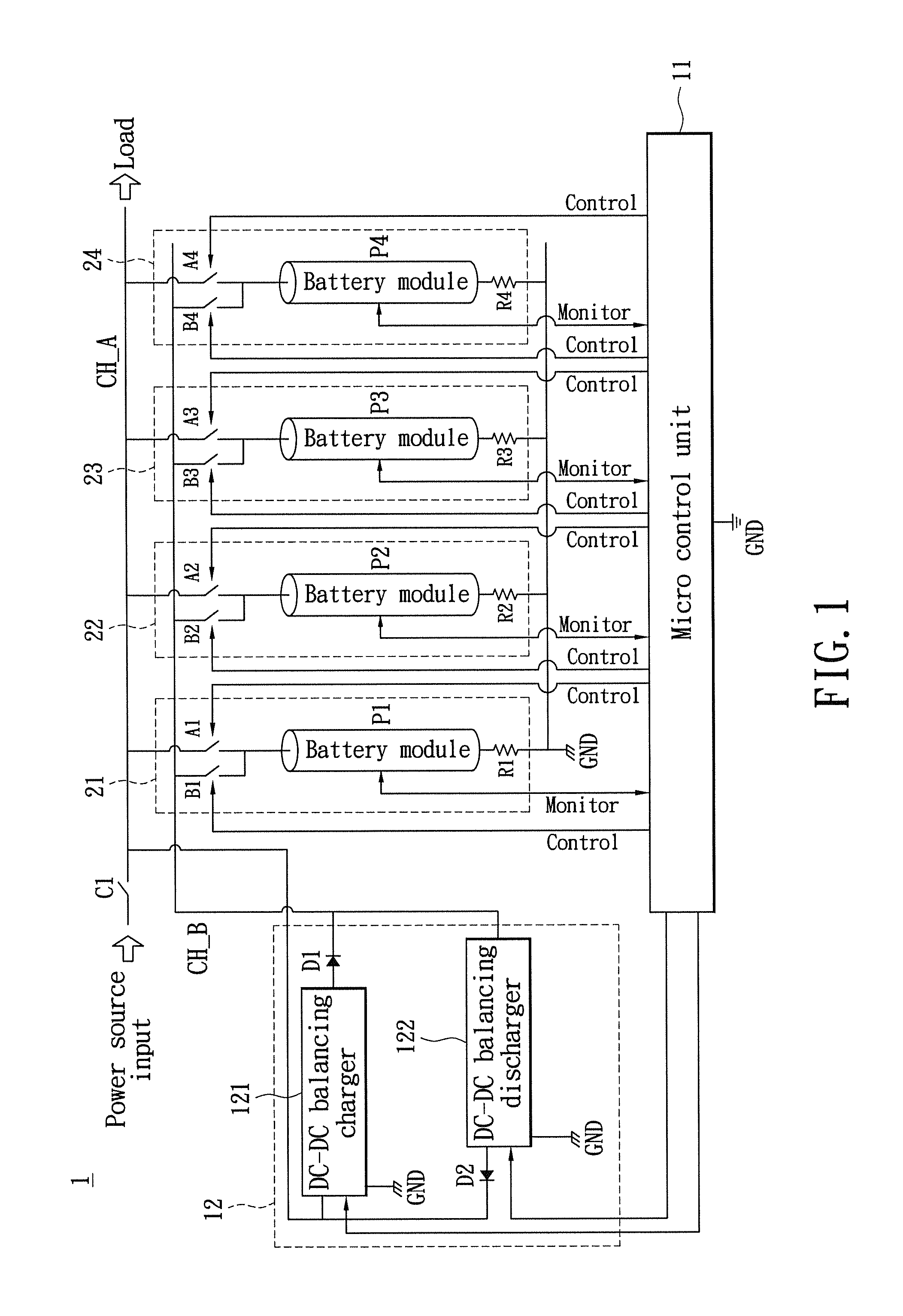
[0017]Please refer to FIG. 1, which shows a circuit diagram according to an embodiment of the battery balancing circuit of the present invention. The battery balancing circuit 1 includes a micro control unit (MCU) 11, a charging-discharging control circuit 12, a load channel CH_A and a charging-discharging channel CH_B. In FIG. 1, the load channel CH_A is connected to a load and to a power source input via a power source switch C1. Both the charging-dischargi...


PUM


Abstract

Disclosed is a battery balancing circuit for balancing the voltages of a reference battery module and a detachable battery apparatus, which has a load channel, a charging-discharging channel, a MCU and a charging-discharging control circuit. The reference battery module and detachable battery apparatus are connected in parallel. The load channel is connected to the reference battery module. The charging-discharging channel is disconnected from the reference battery module. The load and charging-discharging channels are connected to the detachable battery apparatus respectively through a first and a second switches. When the voltage of the detachable battery apparatus is higher or lower than a threshold value, the MCU controls the first and second switches, such that the detachable battery apparatus is connected to the charging-discharging control circuit through the charging-discharging channel and disconnected from the load channel. Then the MCU charges or discharges the detachable battery apparatus through the charging-discharging control circuit.

Description

BACKGROUND OF THE INVENTION[0001]1. Field of the Invention[0002]The present invention relates to a battery balancing circuit, a balancing method and a battery module activation method.[0003]2. Description of Related Art[0004]For energy storage equipment such as an uninterruptible power supply of a server, there are several battery modules connected together in parallel for supplying power to an electric device, e.g. the said server.[0005]However, when a newly added battery module connects to the existing battery module / modules in parallel, inrush current could be generated due to the voltage difference between the newly added and existing battery modules and then inputted into a load such as the aforementioned electric device and / or any of the battery modules. Such inrush current would damage the load and / or the battery module and thereby reduce the electric device's life and / or cause the battery module many problems.[0006]Besides, once a battery module is kept fully-charged or unus...

Claims


Application Information

Patent Timeline
Patent Type & Authority Applications(United States)
IPC IPC(8): H02J7/00
CPCH02J7/0019H02J7/0018
Inventor KUO, KUO-CHENGHSIAO, SUNG-HSIN
Owner TREND POWER TECH CHANGSHU INC
Why Eureka
Try Eureka