Voltage Sag Corrector Using a Variable Duty Cycle Boost Converter

a technology of voltage sag correction and converter, which is applied in the direction of power conversion systems, dc-dc conversion, instruments, etc., can solve the problems of voltage sag, voltage sag, voltage sag, etc., and achieve the effect of reducing the number of voltage sags

Active Publication Date: 2012-10-18
I EWM ACQUISITION LLC
View PDF3 Cites 45 Cited by
  • Summary
  • Abstract
  • Description
  • Claims
  • Application Information

AI Technical Summary

Benefits of technology

[0016](4) in response to detection that the voltage sag is over, turning off the boost converter and clamping excess volt

Problems solved by technology

The reason for occurrence of voltage sags can be due to faults on the grid, and also due to high starting currents drawn by electrical loads (e.g., motors, refrigerators, freezers, air conditioners, etc.) at startup.
Another reason for occurrence of voltage sags is faults in the power provider's transmission or distribution lines.
Additionally, voltage sags can occur frequently in some locations that experience severe weather phenomenon such as lightning, wind, and ice.
For example, lightning strikes a power line and continues to ground, which results in a line-to-ground fault.
Further, since typical power protectors are simple inexpensive electrical devices, having little or no power electronics

Method used


Image

  • Voltage Sag Corrector Using a Variable Duty Cycle Boost Converter
  • Voltage Sag Corrector Using a Variable Duty Cycle Boost Converter
  • Voltage Sag Corrector Using a Variable Duty Cycle Boost Converter

Examples


embodiment 100

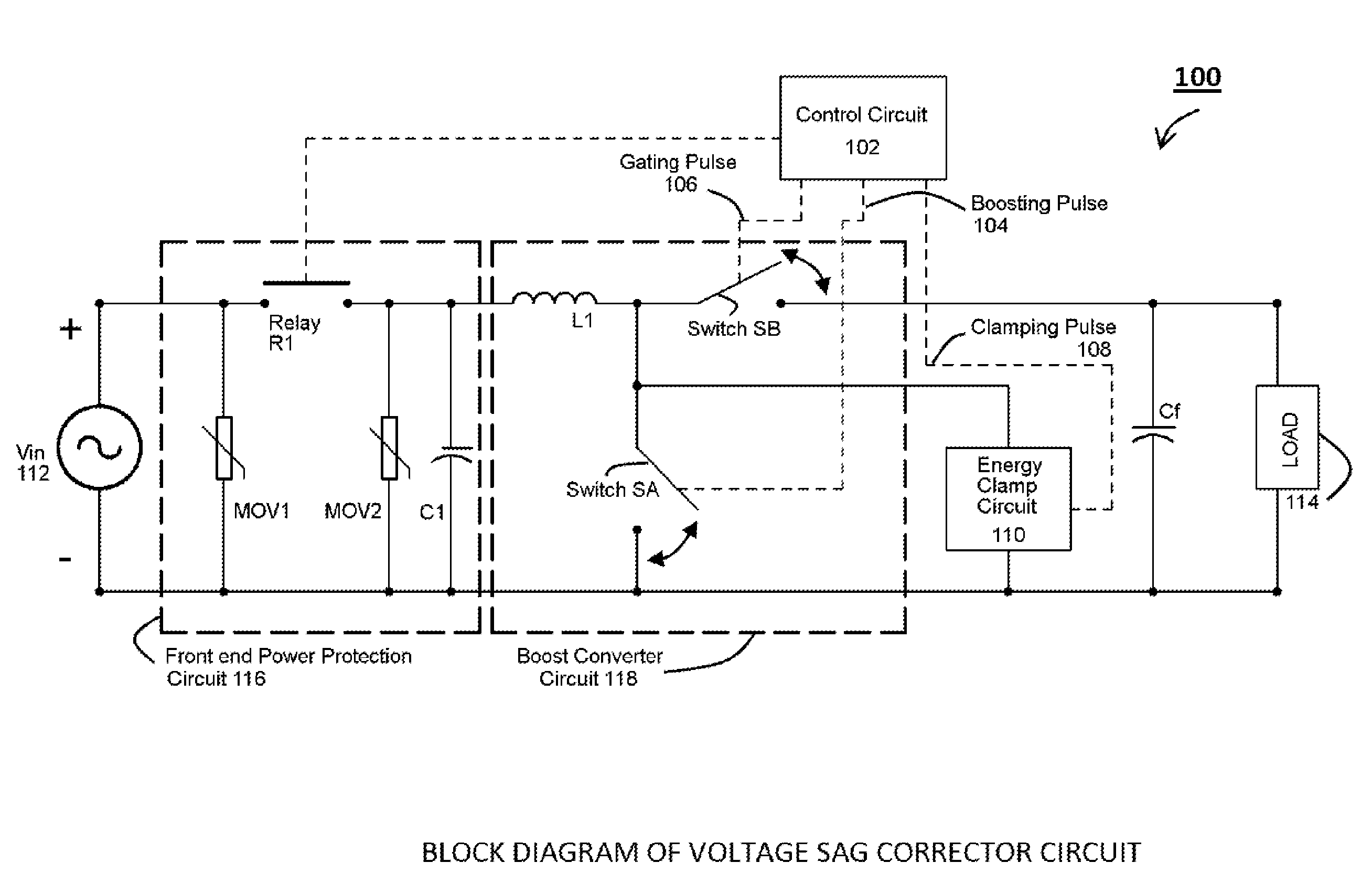
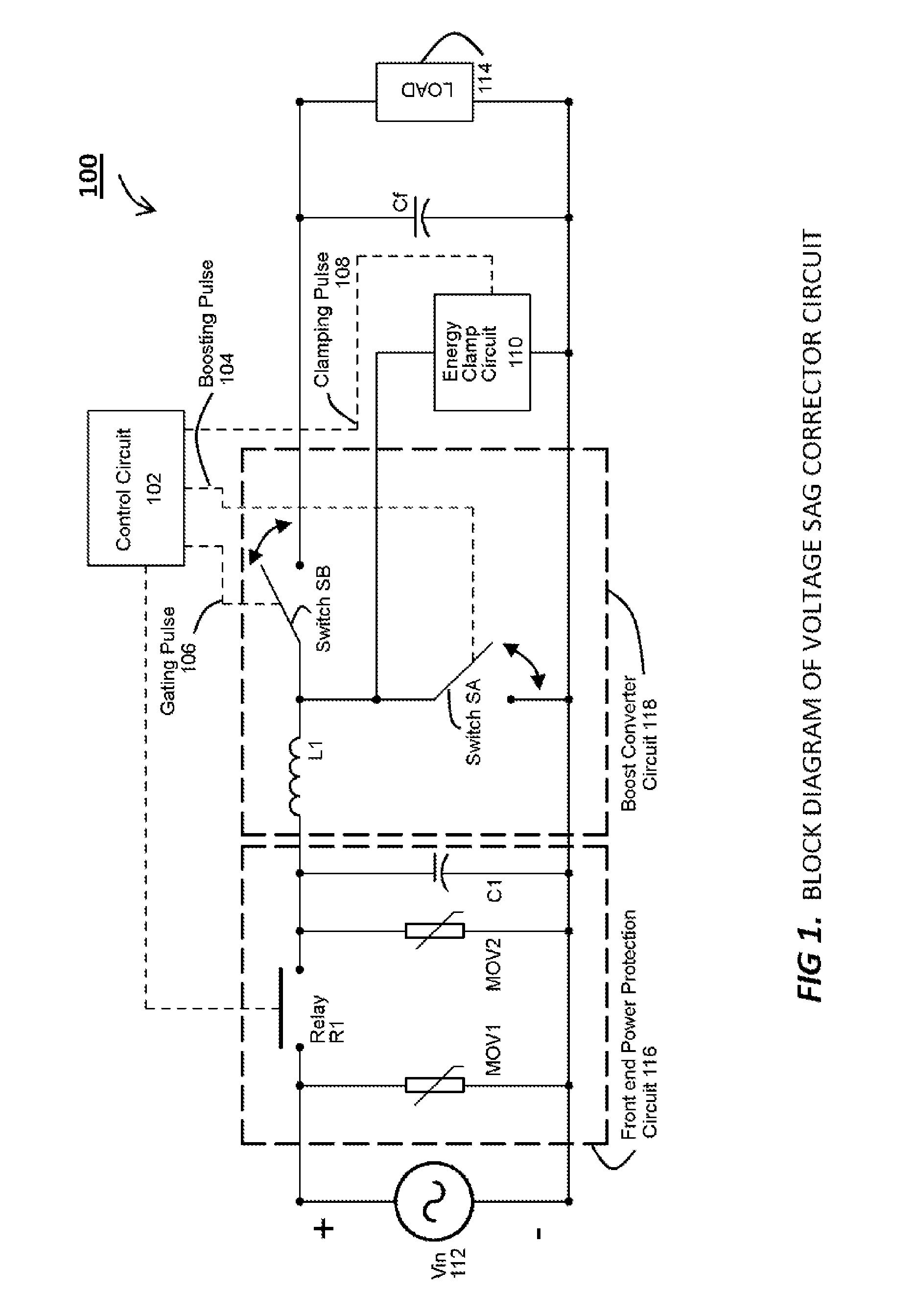
[0026]Referring now to the figures, FIG. 1 illustrates a block diagram of an embodiment 100 of an exemplary sag corrector circuit. As shown, the disclosed sag corrector circuit connects the input AC line voltage (Vin) 112 to the load 114. In the embodiment shown, the sag corrector circuit comprises a front end power protection circuit 116, a boost converter circuit 118, an energy clamp circuit 110, a control circuit 102, and a filter capacitor Cf connected across the load.

[0027]Typically, the front end power protection circuit 116 includes non-linear circuit components such as varistors and other circuit components (e.g., relays etc.) for responding to power line disturbances such as over-voltages, sags, etc. According to one aspect, the front end power protection circuit 116 includes a MOV 1 with a higher voltage rating, a MOV2 with a lower voltage rating, and a relay R1 coupled between the two MOVs.

[0028]Coupled to the front end protection circuit 116 is a boost converter circuit ...

embodiment 300

[0046]Now turning to FIG. 3, an embodiment 300 of a sag corrector circuit is shown. As shown, the disclosed sag corrector circuit connects the AC line voltage (Vin) 112 to the load 114. In the embodiment shown, the sag corrector circuit comprises a front end power protection circuit 116, a boost converter circuit 118, an energy clamp circuit 110, a capacitor Cf connected across the load 114, and a control circuit 102 (for controlling the operation of the power protection circuit 116 and the boost converter circuit 118 via control signals or pulses).

[0047]Typically, the front end power protection circuit 116 includes non-linear circuit components such as varistors and other circuit components for responding to power line disturbances such as over-voltages, sags, etc. According to one aspect, the front end power protection circuit 116 includes a MOV 1 with a higher voltage rating, a MOV2 with a lower voltage rating, and a relay R1 coupled between the two MOVs. In one aspect, the relay...


PUM


Abstract

A sag corrector apparatus for providing voltages temporarily (ride-through) to a load during momentary electrical disturbances in the power supply line. In one embodiment, the disclosed apparatus compensates for voltage sags by using a variable duty cycle boost converter to boost the sagged line voltage to resemble desired voltage levels during occurrence of voltage sags. The boosted voltage available to a connected load during a sag depends on a sequence of operation of various control pulses. Duty cycle of the boost converter is controlled by changing the width (duration) of the control pulses. To prevent voltage shoot-throughs from over-boosting, an energy clamp circuit is provided to dissipate excess energy. Embodiments of the sag corrector circuit can be additionally integrated with power protection functions.

Description

CROSS REFERENCE TO RELATED APPLICATION[0001]This application claims benefit under 35 U.S.C. §119(e) of U.S. Provisional Patent Application No. 61 / 476,532 filed Apr. 18, 2011, and entitled “Voltage Sag Corrector,” which is incorporated herein by reference as if set forth herein in its entirety.TECHNICAL FIELD[0002]The present disclosure relates generally to providing voltages temporarily to a load during momentary electrical disturbances in the power supply line, and more particularly relates to an apparatus that compensates for voltage sags by using a variable duty cycle boost converter to boost the line voltage to predetermined desired voltage levels during occurrence of the voltage sags (a / k / a momentary electrical disturbances), thereby maintaining uptime and productivity across a connected load.BACKGROUND[0003]The five commonly observed power supply line disturbances are voltage surges, voltage sags, overvoltage, under-voltage, and brownouts. Of these, voltage sags account for 90...

Claims


Application Information

Patent Timeline
IPC IPC(8): G05F1/00H02M1/00
CPCH02M2001/0022H02M3/156H02M1/0022
Inventor DIVAN, DEEPAKRAJ MALHAR
Owner I EWM ACQUISITION LLC
Why Eureka
Try Eureka