Compact integral pressurized water nuclear reactor

a nuclear reactor and compact technology, applied in nuclear reactors, nuclear elements, greenhouse gas reduction, etc., can solve the problems of introducing a large-diameter vessel penetration for this purpose, taking primary coolant water outside of the pressure vessel, and integral pwr approach

Active Publication Date: 2012-10-18
BWXT MPOWER INC
View PDF5 Cites 17 Cited by
  • Summary
  • Abstract
  • Description
  • Claims
  • Application Information

AI Technical Summary

Benefits of technology

[0010]In one aspect of the disclosure, an apparatus comprises a pressurized water reactor (PWR) including: a cylindrical pressure vessel defining a sealed volume; a nuclear reactor core disposed in a lower portion of the cylindrical pressure vessel; one or more control rod drive mechanisms (CRDMs) disposed in the cylindrical pressure vessel above the nuclear reactor core; and an annular steam generator surrounding the nuclear reactor core and the CRDM. In some such PWR's, a cylindrical riser is disposed coaxially inside the pressure vessel and inside the annular steam generator and surrounds the nuclear reactor core and the CRDMs, and the steam generator is disposed coaxially inside the cylindrical pressure vessel in an annular volume defined by the cylindrical pressure vessel and the cylindrical riser. In other such PWR's, the steam generator is disposed coaxially outside of and secured with the cylindrical pressure vessel.
[0011]In another aspect of the disclosure, a method is performed in conjunction with a pressurized water reactor (PWR) including a pressure vessel defining a sealed volume containing primary coolant water, a nuclear reactor core disposed in a lower portion of the pressure vessel and immersed in the primary coolant water, a control rod drive mechanisms (CRDMs) disposed in the pressure vessel above the nuclear reactor core and immersed in the primary coolant water, and an annular steam generator disposed outside of and secured with the pressure vessel. The annular steam generator includes tubes having ends in fluid communication with the sealed volume of the pressure vessel and a secondary coolant flow volume in which the tubes are disposed. The secondary coolant flow volume is not in fluid communication with the sealed volume of the pressure vessel. In the method, the PWR is operated to cause nuclear reactivity of the nuclear reactor core to heat the primary coolant water, the primary coolant water is circulated in a circuit including downward flow of primary coolant water outside of the pressure vessel through the tubes of the annular steam generator, and secondary coolant water is flowed upward through the secondary coolant flow volume where the heating and circulating cooperate to convert the primary coolant water to steam.
[0012]In another aspect of the disclosure, an apparatus comprises a pressurized water reactor (PWR) and an annular steam generator. The PWR includes: a pressure vessel defining a sealed volume containing primary coolant water; a nuclear reactor core disposed in a lower portion of the pressure vessel and immersed in the primary coolant water; and one or more control rod drive mechanisms (CRDMs) disposed in the pressure vessel above the nuclear reactor core and immersed in the primary coolant water. The annular steam generator is disposed outside of and secured with the pressure vessel. The annular steam generator includes: tubes having ends in fluid communication with the sealed volume of the pressure vessel; an annular wall that together with the pressure vessel defines a secondary coolant flow volume containing the tubes and not in fluid communication with the sealed volume of the pressure vessel; and a feedwater inlet and a steam outlet in fluid communication with the secondary coolant flow volume.

Problems solved by technology

This approach has the disadvantage of taking primary coolant water outside of the pressure vessel, and of introducing a large-diameter vessel penetration for this purpose.
However, the integral PWR approach has some disadvantages.
Placing the steam generator inside the pressure vessel increases the size of the pressure vessel, which has disadvantages in terms of manufacturing cost, transport cost (e.g., a larger rail transport car and / or specialized rail system), site considerations (e.g., a deeper subterranean containment structure), and safety (e.g., more difficult to maintain seal integrity as the size of the pressure vessel increases).

Method used


Image

  • Compact integral pressurized water nuclear reactor
  • Compact integral pressurized water nuclear reactor
  • Compact integral pressurized water nuclear reactor

Examples


Embodiment Construction

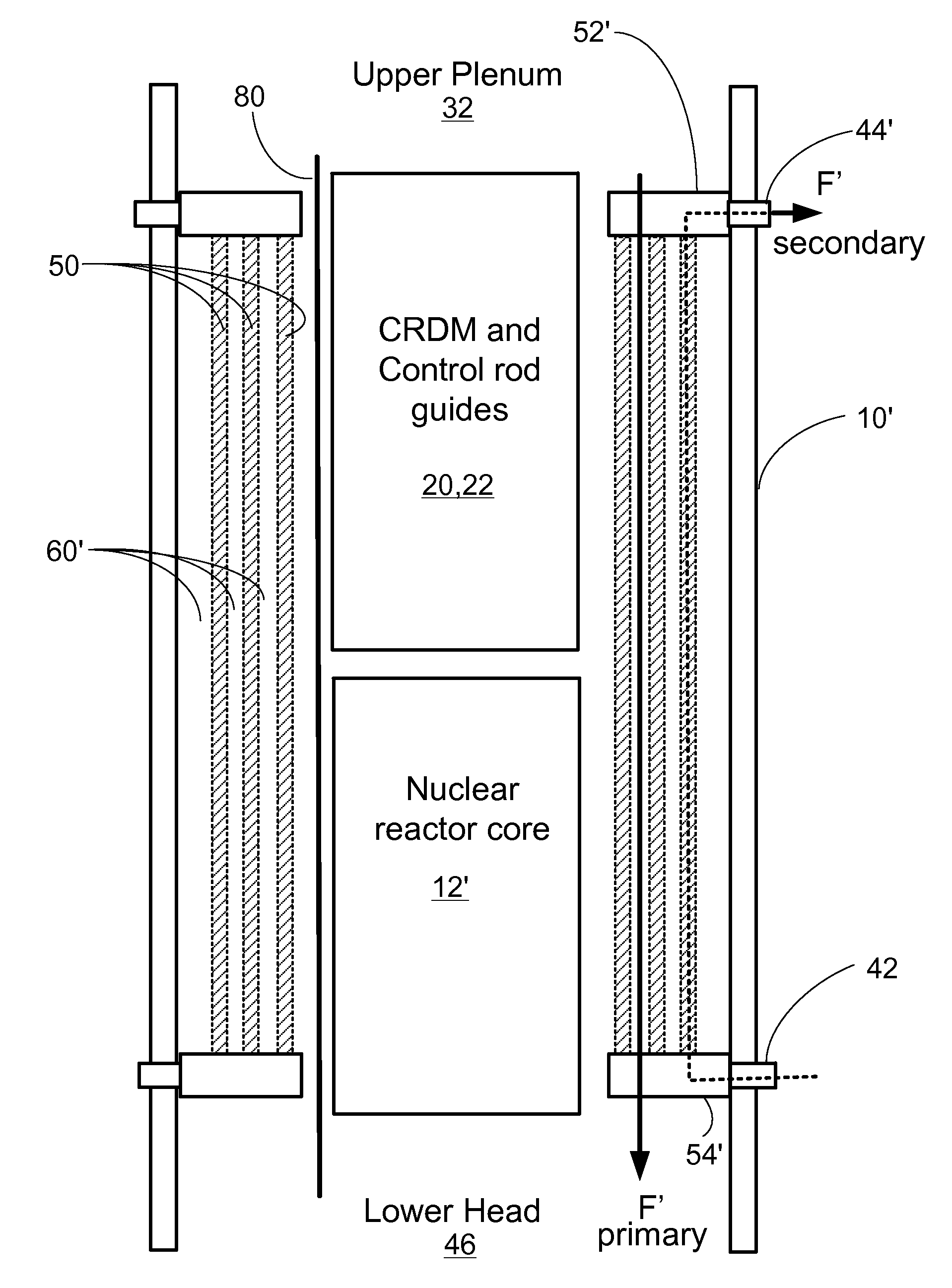
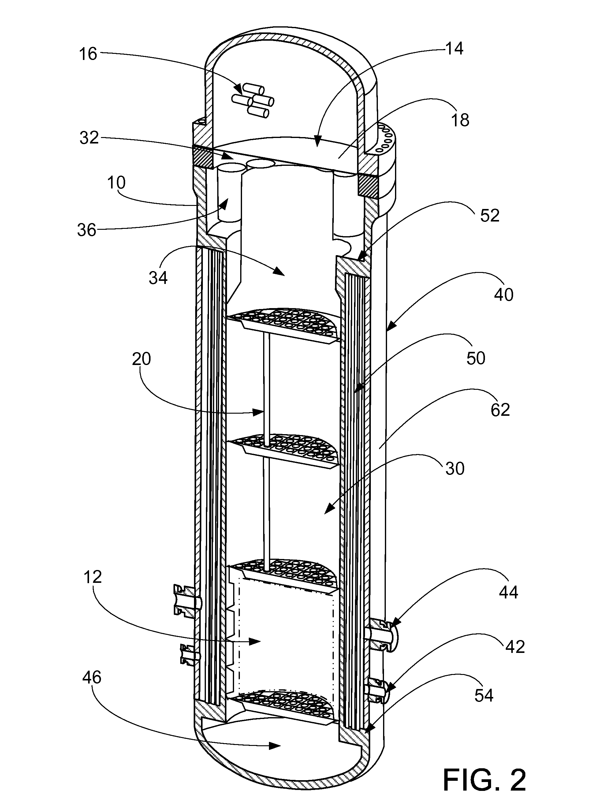
[0018]With reference to FIGS. 1 and 2, an illustrative nuclear reactor of the pressurized water reactor (PWR) type includes a pressure vessel 10 and a nuclear reactor core 12 disposed in a lower portion of the cylindrical pressure vessel 10. The pressure vessel 10 defines a sealed volume that, when the PWR is operational, contains primary coolant water in a subcooled state. Toward this end, the PWR includes an internal pressurizer disposed at the top of the pressure vessel 10. The internal pressurizer includes a steam bubble volume 14 and heaters 16 (which in some embodiments are resistive heaters) for heating water to generate the steam bubble 14. The internal pressurizer may also include other components, such as a baffle plate 18 separates the internal pressurizer volume from the remainder of the sealed volume of the pressure vessel 10, spargers (not shown) for injecting cooler water or steam into the steam bubble volume 14 to produce a reduction in pressure, and so forth.

[0019]R...


PUM


Abstract

A pressurized water reactor (PWR) includes a cylindrical pressure vessel defining a sealed volume, a nuclear reactor core disposed in a lower portion of the cylindrical pressure vessel, one or more control rod drive mechanisms (CRDMs) disposed in the cylindrical pressure vessel above the nuclear reactor core, and an annular steam generator surrounding the nuclear reactor core and the CRDM. In some such PWR, a cylindrical riser is disposed coaxially inside the pressure vessel and inside the annular steam generator and surrounds the nuclear reactor core and the CRDM, and the steam generator is disposed coaxially inside the cylindrical pressure vessel in an annular volume defined by the cylindrical pressure vessel and the cylindrical riser. In other such PWR, the steam generator is disposed coaxially outside of and secured with the cylindrical pressure vessel.

Description

BACKGROUND[0001]The following relates to the nuclear reactor arts, electrical power generation arts, and related arts.[0002]Nuclear reactors employ a reactor core comprising a mass of fissile material, such as a material containing uranium oxide (UO2) that is enriched in the fissile 235U isotope. Primary coolant water, such as light water (H2O) or heavy water (D2O) or some mixture thereof, flows through the reactor core to extract heat for use in heating secondary coolant water to generate steam that is then used for some other useful purpose. For electrical power generation, the steam is used to drive a generator turbine. In thermal nuclear reactors, the water also serves as a neutron moderator that thermalizes neutrons, which enhances reactivity of the fissile material. Various reactivity control meachanisms, such as mechanically operated control rods, chemical treatment of the primary coolant with a soluble neutron poison, or so forth are employed to regulate the reactivity and r...

Claims


Application Information

Patent Timeline
Patent Type & Authority Applications(United States)
IPC IPC(8): G21C15/00
CPCG21C1/326G21C7/12G21C15/00G21D1/006Y02E30/39G21C13/02Y02E30/32Y02E30/00Y02E30/30G21C13/00
Inventor MALLOY, JOHN D.EDWARDS, MICHAEL J.
Owner BWXT MPOWER INC
Why Eureka
Try Eureka