Speaker

a technology for speakers and drivers, applied in the field of speakers, can solve problems such as the difficulty of improving the driving efficiency of speakers, and achieve the effect of suppressing the distortion of speakers and improving driving efficiency

Inactive Publication Date: 2012-10-18
PANASONIC CORP
View PDF0 Cites 23 Cited by
  • Summary
  • Abstract
  • Description
  • Claims
  • Application Information

AI Technical Summary

Benefits of technology

[0005]With such a configuration, the distortion of the speaker can be suppressed and the driving efficiency can be improved.

Problems solved by technology

As a result, it is difficult to improve the driving efficiency of a speaker.

Method used


Image

  • Speaker
  • Speaker
  • Speaker

Examples


first exemplary embodiment

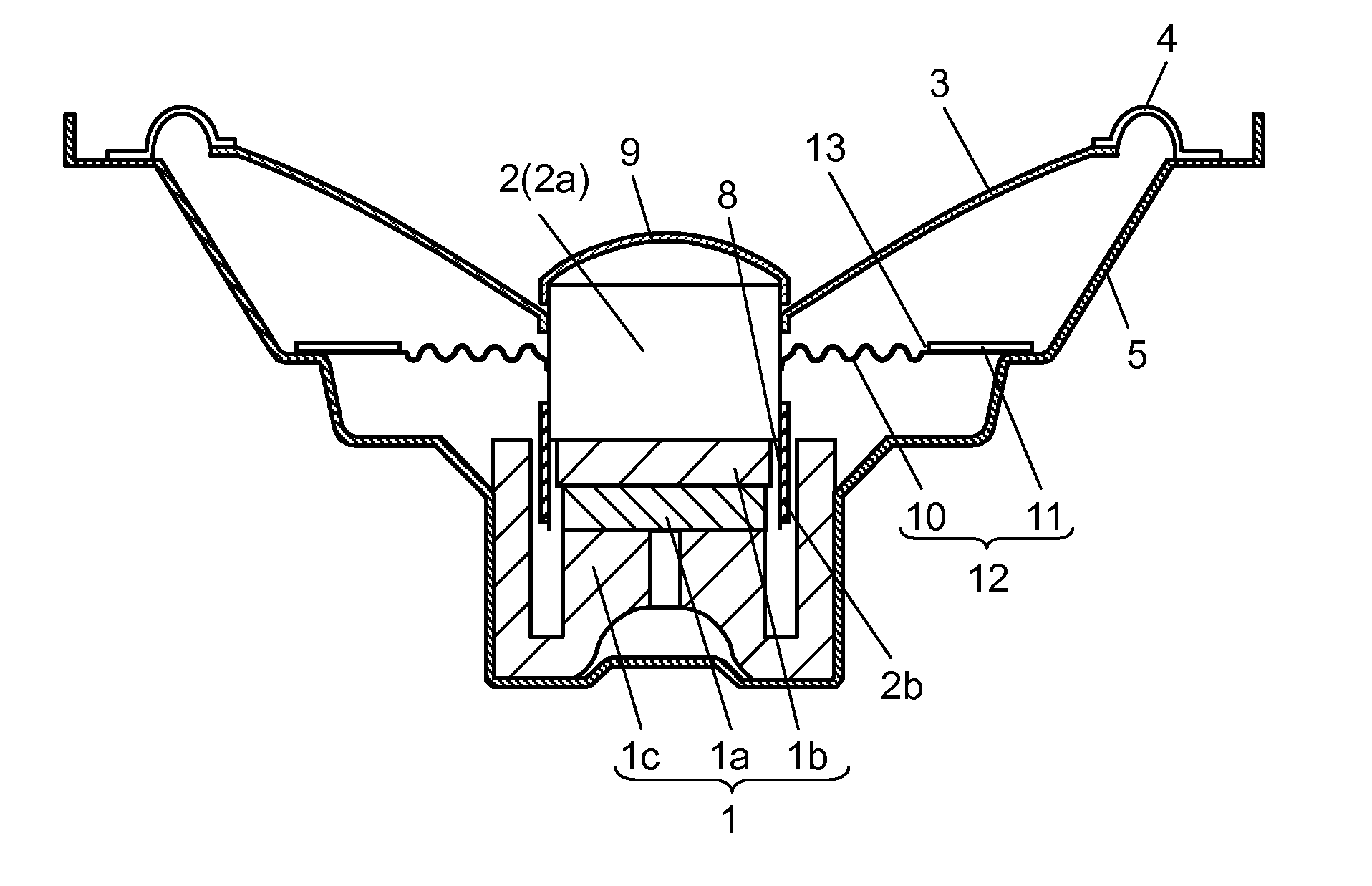
[0013]Hereinafter, a first exemplary embodiment of the present invention is described with reference to drawings. In the description, the same reference numerals are given to the same configurations as those mentioned above as a background art.

[0014]FIG. 1A is a sectional view showing a speaker in accordance with a first exemplary embodiment of the present invention. Magnetic circuit 1 disposed in the middle of the bottom of bowl-shaped frame 5 is constructed by combining and bonding disk-shaped magnet 1a, disk-shaped plate 1b and cylindrical yoke 1c. Magnetic gap 8 opening upward in magnetic circuit 1 is formed between the inner peripheral side surface of the side wall of yoke 1c and the outer peripheral side surface of disk-shaped plate 1b.

[0015]Furthermore, voice coil unit 2 (hereinafter, referred to as coil unit 2) has a structure in which coil 2b is wound around the outer periphery of cylindrical main body 2a. In the structure, coil unit 2 is inserted into magnetic gap 8 and m...

second exemplary embodiment

[0028]Diaphragm 3, coil unit 2 and corrugated structure portion 10, which are located in a region between edge 4 and leaf spring 11, can be regarded as an integrated rigid body. Therefore, when the distance between edge 4 and leaf spring 11 is increased, the rolling of coil unit 2 can be suppressed and the distortion can be reduced.

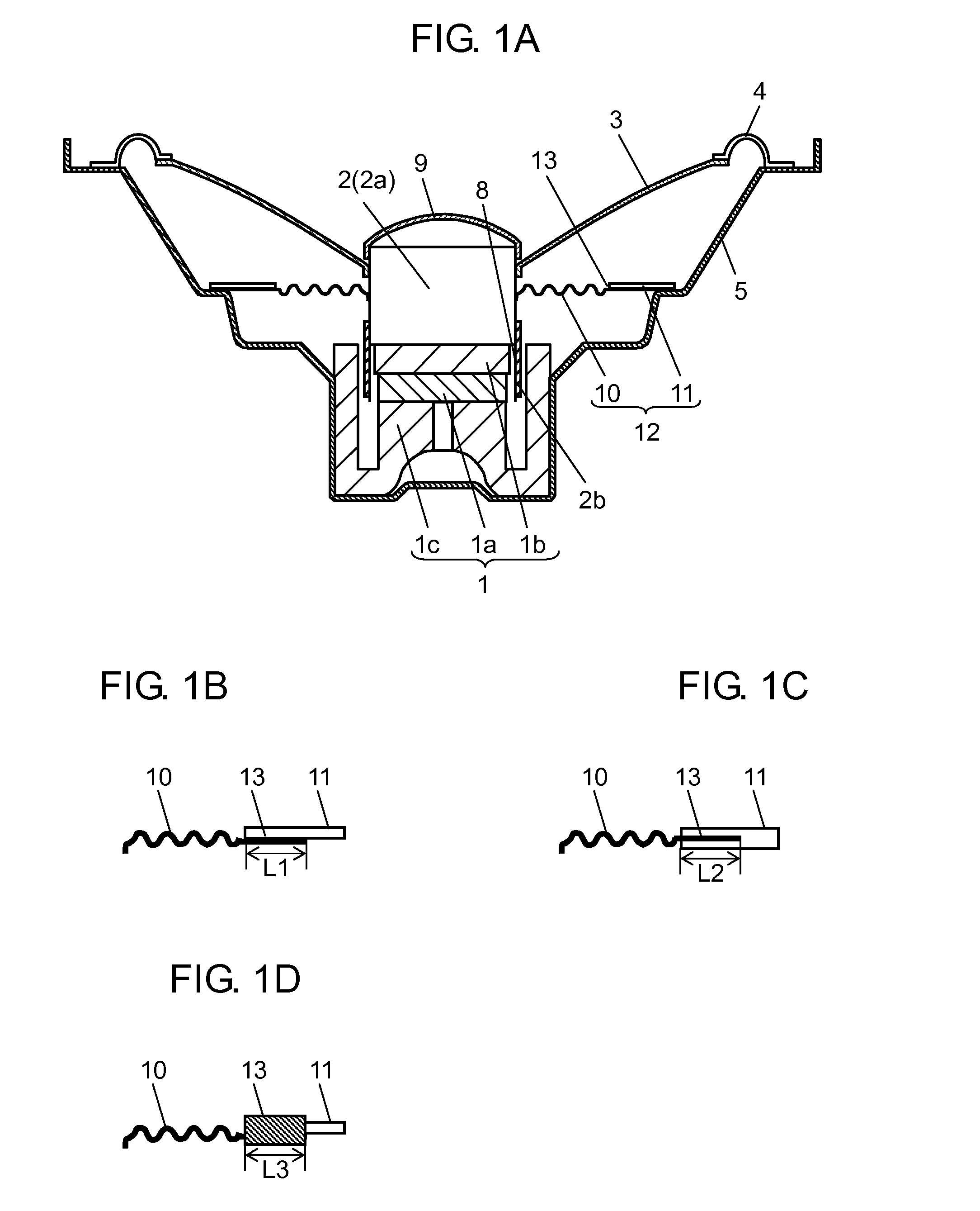
[0029]FIG. 2 is a partially cutaway sectional view showing a speaker in accordance with the second exemplary embodiment of the present invention. This speaker is provided with linearly extending portion 14 extending from the outer periphery of the corrugated structure portion 10 to the position at the similar height as that of magnetic gap 8. Linearly extending portion 14 is coupled to leaf spring 11 at coupling portion 13, and leaf spring 11 is coupled to frame 5.

[0030]Thus, the distance between edge 4 and leaf spring 11 can be increased as compared with the structure shown in FIG. 1A. As a result, the effect of suppressing the rolling of coil unit 2 can...


PUM


Abstract

A damper, which is an element of a speaker and suppresses the rolling of a voice coil unit, includes a corrugated structure portion at its inner periphery and a leaf spring at its outer periphery. By coupling the corrugated structure portion to the voice coil unit and coupling the leaf spring to the frame, the distortion of a speaker can be reduced and the driving efficiency can be improved.

Description

TECHNICAL FIELD[0001]The present invention relates to a speaker.BACKGROUND ART[0002]Japanese Patent Unexamined Publication No. 2004-7332 discloses a speaker shown in FIG. 3 in which voice coil unit 2 that is movably disposed on magnetic circuit 1 is coupled to the inner peripheral end of diaphragm 3 and the outer peripheral end of diaphragm 3 is coupled to frame 5 via edge 4. In this speaker, the rear surface of diaphragm 3 is coupled to frame 5 via suspension holder 6 and edge 7. Furthermore, edges 4 and 7 are allowed to protrude in the opposite directions to each other, thereby allowing the vertical amplitude to be vertically symmetric. Thus, the distortion of the speaker is reduced.[0003]However, when such a speaker structure is employed, suspension holder 6 is formed so as to have at least the same level of rigidity as that of diaphragm 3. This causes the driving load of magnetic circuit 1 to increase. As a result, it is difficult to improve the driving efficiency of a speaker.S...

Claims


Application Information

Patent Timeline
Patent Type & Authority Applications(United States)
IPC IPC(8): H04R9/02H04R9/06
CPCH04R9/043H04R1/28H04R7/26H04R9/02
Inventor FUNAHASHI, OSAMU
Owner PANASONIC CORP
Why Eureka
Try Eureka