Turbocharger

a technology of turbocharger and rotor shaft, which is applied in the direction of liquid fuel engines, machines/engines, sliding contact bearings, etc., can solve the problems of lubricant oil supplied to the first outer peripheral surfaces, difficulty in improving oil sealing properties, and likely scattered along the rotor shaft. , to achieve the effect of relieving the supply pressure of lubricant oil

Active Publication Date: 2012-10-18
TOYOTA IND CORP +1
View PDF5 Cites 13 Cited by
  • Summary
  • Abstract
  • Description
  • Claims
  • Application Information

AI Technical Summary

Benefits of technology

[0013]In the turbocharger of the present invention, the groove and the discharge passage make the lubricant oil supplied to the outer peripheral surfaces of the bearing portions, less likely to be scattered along the rotor shaft. For this reason, the lubricant oil supplied to the outer peripheral surfaces is prevented from coming into contact with the members rotating together with the rotor shaft and others. Therefore, it is feasible to prevent the lubricant oil supplied to the outer peripheral surfaces from being scattered over a wide range by centrifugal force with rotation of the members rotating together with the rotor shaft and others. As a result, the lubricant oil becomes less likely to leak into the exhaust on the turbine wheel side or into the intake air on the compressor wheel side through the clearance between the housing and the rotor shaft.
[0016]The turbocharger may be configured as follows: the housing has a compartment wall located between the bearing chamber and the turbine wheel, the groove is formed at least in the outer peripheral surface of the bearing portion located on the turbine wheel side, and the discharge passage is formed so that the lubricant oil comes into contact with the compartment wall. In this case, the lubricant oil discharged from the discharge passage comes into contact with the compartment wall on the turbine wheel side which will be raised to high temperature. This configuration allows the compartment wall to be cooled.
[0019]In the present invention, the lubricant oil is supplied through the first oil feed passage and the outside oil feed chamber to the first outer peripheral surfaces of the both bearing portions of the semi-floating bearing. The lubricant oil supplied to the first outer peripheral surfaces is subjected to the supply pressure from the first oil feed passage side, to move toward the turbine wheel and toward the compressor wheel. Since the groove extending in the circumferential direction is formed in at least one of the first outer peripheral surfaces, the lubricant oil supplied to the first outer peripheral surface with the grooved formed therein flows into the groove. This relieves the supply pressure of the lubricant oil. The lubricant oil in the groove moves downward along the groove by gravity. Since the discharge passage opposed to the groove and configured to discharge the lubricant oil in the groove downward is formed in the bearing housing, the lubricant oil moving downward along the groove is guided to the discharge passage to be discharged downward. The lubricant oil is also supplied through the second oil feed passage and the inside oil feed chamber to the first inner peripheral surfaces of the respective bearing portions of the semi-floating bearing.
[0020]In the turbocharger of the present invention, the groove and the discharge passage make the lubricant oil supplied to the first outer peripheral surfaces, less likely to be scattered along the rotor shaft. For this reason, the lubricant oil supplied to the first outer peripheral surfaces is prevented from coming into contact with the members rotating together with the rotor shaft and others. Therefore, it is feasible to prevent the lubricant oil supplied to the first outer peripheral surfaces from being scattered over a wide range by centrifugal force with rotation of the members rotating together with the rotor shaft and others. As a result, the lubricant oil becomes less likely to leak into the exhaust on the turbine wheel side or into the intake air on the compressor wheel side through the clearance between the housing and the rotor shaft.

Problems solved by technology

In the above-described conventional turbocharger, however, the lubricant oil supplied to the first outer peripheral surfaces is subjected to the supply pressure from the first oil feed passage side and thus likely to be scattered along the rotor shaft.
As a result, the scattered lubricant oil can leak through the clearance between the housing and the rotor shaft into the exhaust on the turbine wheel side or into the intake air on the compressor wheel side, with difficulties in improvement of oil-sealing properties.

Method used


Image

  • Turbocharger
  • Turbocharger
  • Turbocharger

Examples


first embodiment

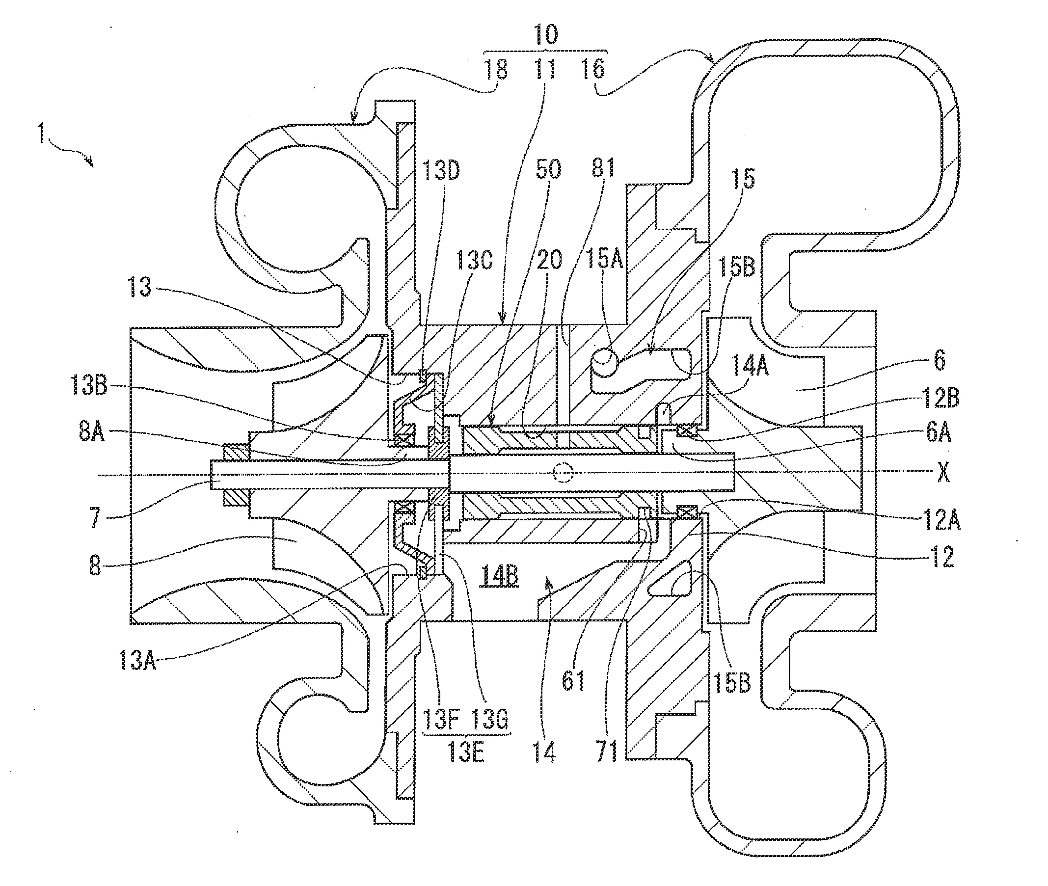
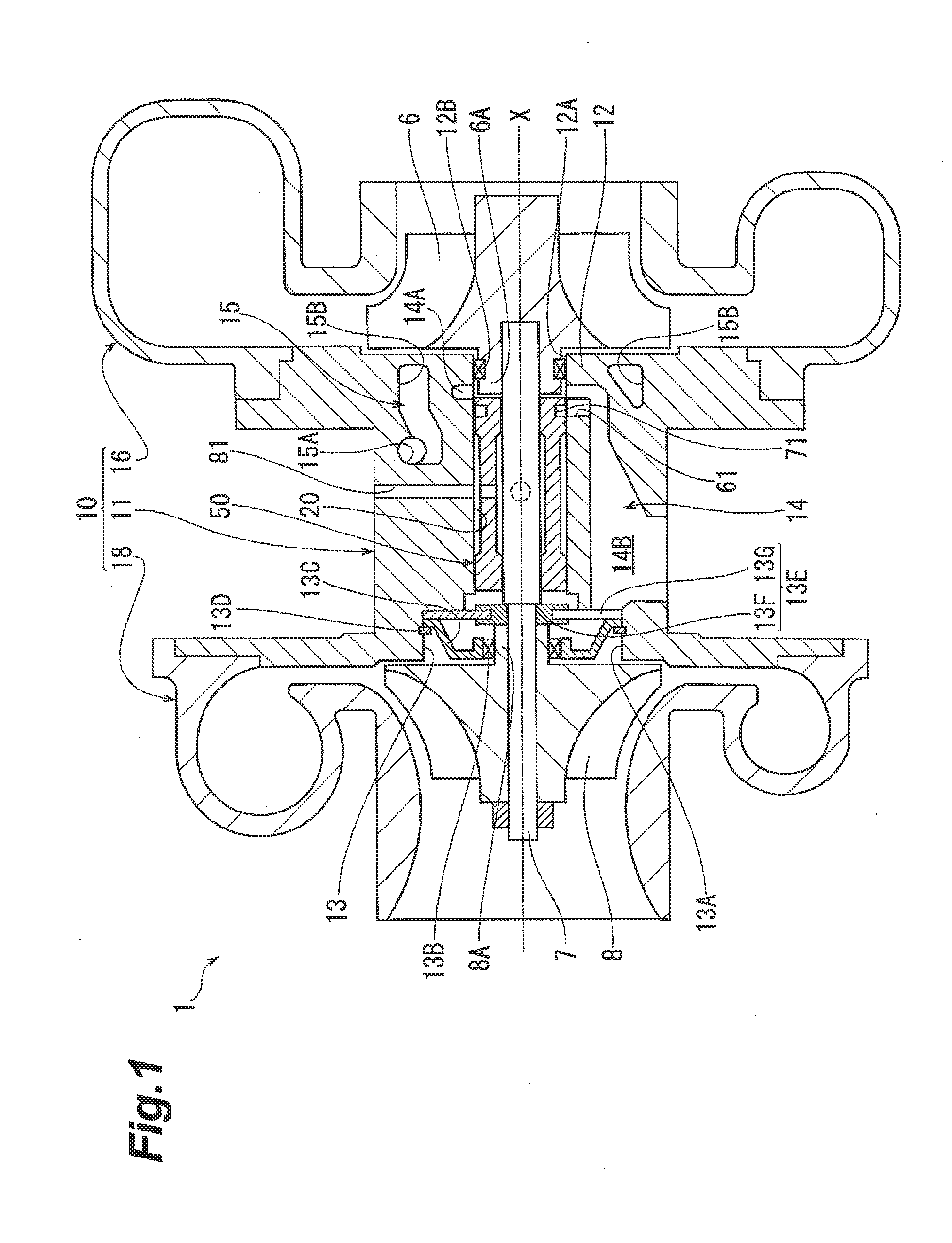
[0036]As shown in FIG. 1, a turbocharger 1 of the first embodiment is provided with a housing 10. The housing 10 has a turbine housing 16 housing a turbine wheel 6, a compressor housing 18 housing a compressor wheel 8, and a bearing housing 11. The bearing housing 11 is located between the turbine housing 16 and the compressor housing 18.

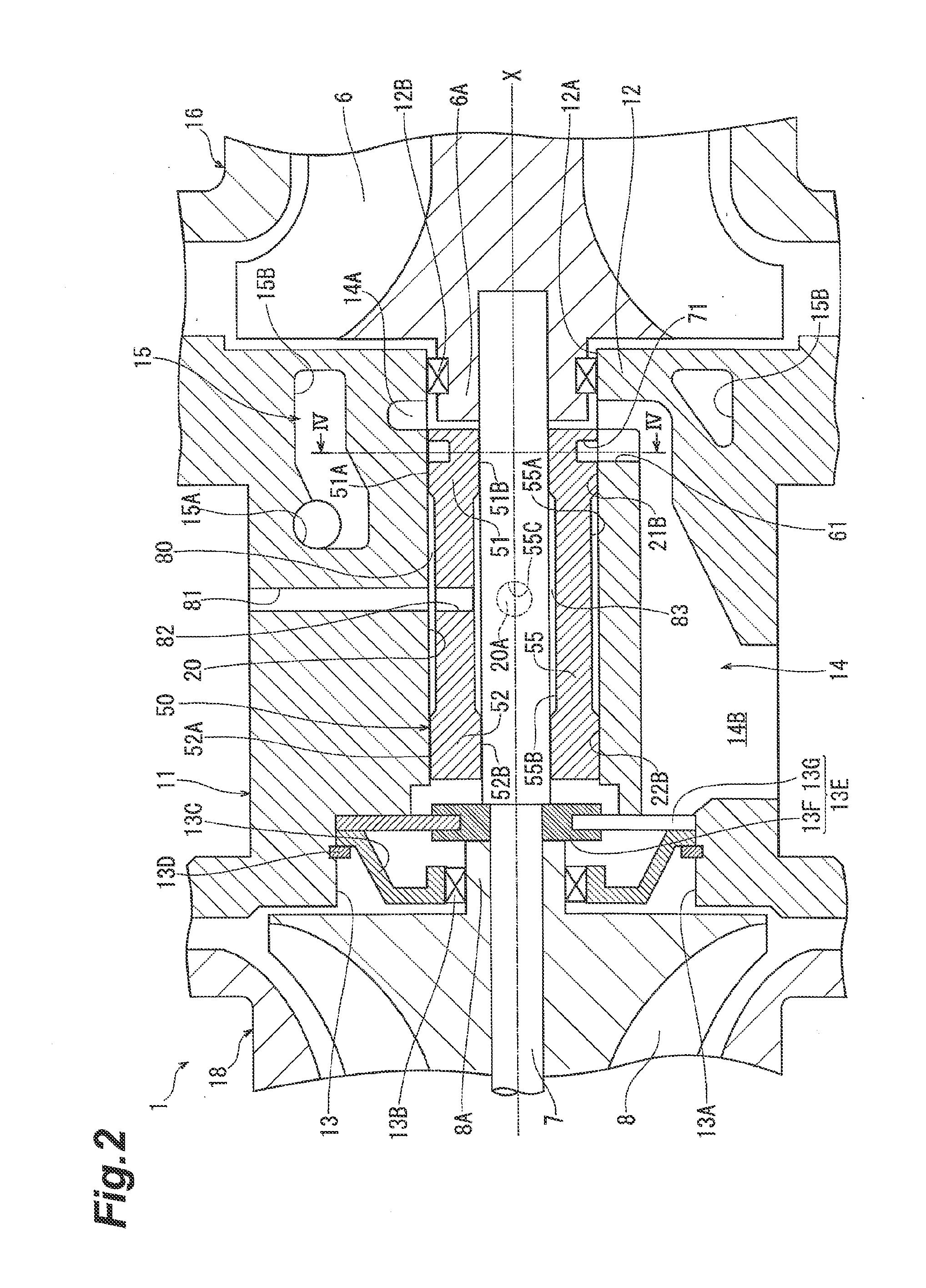
[0037]As shown in FIG. 2, a bearing chamber 20 is formed in the bearing housing 11. The bearing chamber 20 is a cylindrical space with a central axis on a shaft center X. The turbine housing 16 is joined to one side face of the bearing housing 11 in the direction of the shaft center X. The compressor housing 18 is joined to the other side face of the bearing housing 11 in the direction of the shaft center X.

[0038]The turbocharger 1 is provided with a semi-floating bearing 50 of a stepped cylinder shape, and a rotor shaft 7 of a cylindrical shaft shape. The semi-floating bearing 50 is arranged in the bearing chamber 20 and housed in the bearing chamb...

second embodiment

[0061]As shown in FIGS. 6 to 8, the turbocharger 2 of the second embodiment employs a discharge passage 62 and a water jacket 215, instead of the discharge passage 61 and the water jacket 15 in the turbocharger 1 of the first embodiment. In the turbocharger 2, a recovery groove 72 and a discharge passage 63 are provided on the compressor wheel 8 side. The other configuration is the same as that of the turbocharger 1.

[0062]In the turbocharger 2, as shown in FIG. 6, the discharge passage 62 is formed on the turbine wheel 6 side of the bearing chamber 20 in the bearing housing 11. The discharge passage 62 penetrates the bearing housing 11 obliquely downward so as to become closer to the part of the compartment wall 12 located below the shaft center X, whereby it is formed in a thin hole form. The upper end of the discharge passage 62 has an opening in the second inner peripheral surface 21B on the turbine wheel 6 side to be opposed to the recovery groove 71 from bottom and communicated...


PUM


Abstract

A turbocharger is provided with a rotor shaft and a semi-floating bearing arranged in a bearing chamber and rotatably supporting the rotor shaft. The semi-floating bearing has a pair of bearing portions located at two longitudinal ends. A region between the pair of bearing portions in an outer peripheral surface of the semi-floating bearing and an inner peripheral surface of the bearing chamber constitute an outside oil feed chamber to supply a lubricant oil to outer peripheral surfaces of the pair of bearing portions. A groove extending in a circumferential direction is formed in the outer peripheral surface of at least one of the bearing portions. An oil feed passage to supply the lubricant oil to the outside oil feed chamber and a discharge passage opposed to the groove and configured to discharge the lubricant oil in the groove downward are formed in the bearing housing.

Description

BACKGROUND OF THE INVENTION[0001]1. Field of the Invention[0002]The present invention relates to a turbocharger.[0003]2. Related Background Art[0004]A conventional turbocharger is one disclosed in Japanese Patent Application Laid-open No. 9-242554 (U.S. Pat. No. 5,993,173 corresponding thereto). This turbocharger is provided with a housing having a bearing housing in which a bearing chamber is formed, a semi-floating bearing arranged in the bearing chamber, and a rotor shaft rotatably supported by the semi-floating bearing. A turbine wheel and a compressor wheel are coupled to the two ends of the rotor shaft.[0005]The semi-floating bearing has a pair of bearing portions formed at the two longitudinal ends, and an intermediate portion connecting the two bearing portions. Formed in each of the two bearing portions are a first outer peripheral surface of a cylindrical shape, and a first inner peripheral surface arranged coaxially with the first outer peripheral surface and rotatably su...

Claims


Application Information

Patent Timeline
Patent Type & Authority Applications(United States)
IPC IPC(8): F04D29/056F04D29/063
CPCF16C17/02F16C27/02F16C17/18F16C33/1045F16C2360/24F16C33/74
Inventor IWATA, HIROMUUESUGI, TSUYOSHI
Owner TOYOTA IND CORP
Why Eureka
Try Eureka