
Method and control unit for detecting a safety-critical impact of an object on a vehicle

a technology of safety-critical impact and control unit, which is applied in the direction of process and machine control, pedestrian/occupant safety arrangement, instruments, etc., can solve the problems of increasing the computation power of the processor, requiring an increased effort to determine the yaw performance of the vehicle, etc., and achieves optimized evaluation of yaw performance, time-saving effect, and strong influence of possible measurement errors

Inactive Publication Date: 2012-10-18
ROBERT BOSCH GMBH
View PDF5 Cites 7 Cited by
  • Summary
  • Abstract
  • Description
  • Claims
  • Application Information

AI Technical Summary

Benefits of technology

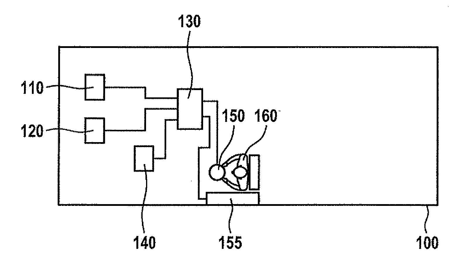
[0010]Furthermore, the present invention provides an example control unit which is designed to perform and implement the steps of the example method according to the present invention. One object on which the present invention is based may also be achieved rapidly and efficiently through this embodiment variant of the present invention in the form of a control unit.
[0021]It is favorable in particular if a step of activation of a passenger protection device is also provided when a safety-critical impact of an object on the vehicle is detected during the step of detection. Such a specific embodiment of the present invention offers the advantage that a passenger protection device is also activated to protect occupants of the vehicle, depending on the detection of a safety-critical impact of an object on the vehicle. This further increases the personal safety of vehicle occupants through measures that are technically simple to implement.

Problems solved by technology

However, this requires an increased effort to determine the yaw performance of the vehicle.
However, continuous monitoring of the yaw acceleration at all times while the vehicle is in motion would require an unnecessary increase in the computation power of the processor.

Method used


Image

  • Method and control unit for detecting a safety-critical impact of an object on a vehicle
  • Method and control unit for detecting a safety-critical impact of an object on a vehicle
  • Method and control unit for detecting a safety-critical impact of an object on a vehicle

Examples


Embodiment Construction

[0026]The same or similar elements may be provided with the same or similar reference numerals in the figures, so it is not necessary to repeat the description. Furthermore, the figures and their description contain numerous features in combination. These features may also be considered individually or combined into other combinations, which are not described here explicitly. Furthermore, the present invention is explained below using different dimensions and measures, but the present invention is not to be understood as being limited to these measures and dimensions. Furthermore, example method steps according to the present invention may also be repeated and may be executed in a different order than the order described here. If an exemplary embodiment includes an “and / or” linkage between a first feature and a second feature, this may be read as meaning that the exemplary embodiment according to one specific embodiment includes both the first feature and the second feature and acco...


PUM


Abstract

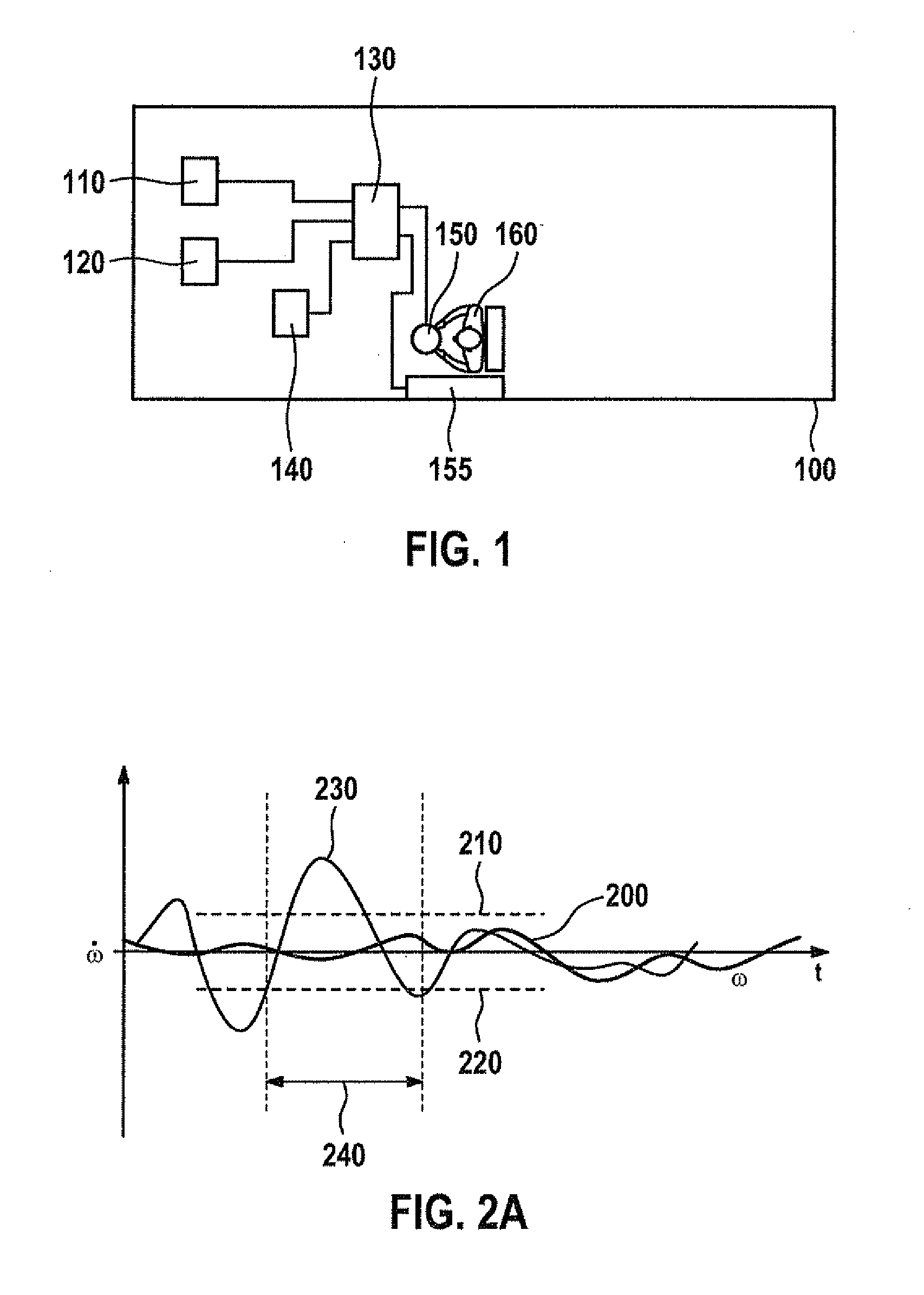
A method for detecting a safety-critical impact of an object on a vehicle is described. The method has a first step of obtaining a starting signal for starting a time measurement, to establish the start of a subsequent predetermined time span. In addition, the method has a step of receiving a signal representing a yaw acceleration of the vehicle, the signal being received during the predetermined time span. Finally, the method has a step of detecting the safety-critical impact of the object on the vehicle detecting the safety-critical impact of an object on the vehicle when the signal within the predetermined time span has a value that is outside a threshold value range or when the signal after the predetermined time span has a value derived from the signal that is outside of a threshold value range.

Description

FIELD OF THE INVENTION[0001]The present invention relates to a method, a control unit, and a computer program product for detecting a safety-critical impact.BACKGROUND INFORMATION[0002]The activation of restraining devices in a vehicle collision is determined in principle by the type of accident (crash type) and the severity of the accident (crash severity). Conventionally, both the type of crash and the crash severity to be expected are evaluated by the combined signal evaluation of acceleration sensors, rolling rate sensors and pressure sensors as well as forward-looking sensors (for example, radar sensors) which are integrated into the vehicle. The signal characteristics and the change in speed in both longitudinal and lateral directions are evaluated via the acceleration sensors; the continuation of a vehicle rollover movement about the longitudinal axis is evaluated via the rolling rate; two-dimensional collision contacts are detected quickly via the pressure sensors, and the c...

Claims


Application Information

Patent Timeline
IPC IPC(8): B60R21/013
CPCB60R21/0132B60R21/0133B60R21/01332
Inventor LANG, GUNTHERDOERR, ALFONSRITTLER, STEPHAN
Owner ROBERT BOSCH GMBH
Learn More