
Agricultural implement with accumulator suspension

a technology of accumulator and agricultural implement, which is applied in the direction of fluid-pressure actuator, thinning machine, agricultural machines, etc., can solve the problems of cracks in the frame, large forces generated by upward and downward movement of agricultural tools, and relatively rigid connection of agricultural tools with the frame, so as to simplify the incorporation and maintenance of the fluid system, and achieve the effect of advantageously simplifying the fluid system

Active Publication Date: 2012-10-25
LELY PATENT
View PDF2 Cites 0 Cited by
  • Summary
  • Abstract
  • Description
  • Claims
  • Application Information

AI Technical Summary

Benefits of technology

[0030]The fluid system further comprises an accumulator connected to the conduit assembly and in flow connection therewith to accumulate fluid. The accumulator can compensate for sudden pressure increases in the conduit assembly as a result of forces acting on the subframe. This means that the accumulator can act as a suspension.
[0035]The agricultural implement according to the invention can advantageously provide an improved suspension of the subframe with respect to the main frame. When the subframe is kept in the lifting-mode, sudden forces acting on the cylinder can be compensated by the accumulator as a result of the open flow connection between the accumulator and the cylinder. According to the invention, the open flow connection in the first closing position “1” is only achieved after the supply of hydraulic liquid from the pump to the cylinder has stopped. This means that hydraulic liquid is hardly or not supplied to the accumulator during the supply of hydraulic liquid to the cylinder. Therefore, the pressure in the accumulator is only established when the flow connection between the second port II to the accumulator and the third port III to the cylinder is open. This means that the pressure will be lower than in the case when the second port II to the accumulator would already be open during the supply of hydraulic liquid from the pump. As a result thereof, the accumulator can advantageously confer improved resilient properties to the cylinder. This may result in a softer and less rigid suspension. Collisions of agricultural tools affecting the cylinder can be better compensated by the connection of the accumulator with the pressure valve according to the invention.
[0037]In an embodiment of the agricultural implement according to the invention, the valve assembly further comprises a supply line, a cylinder line, an accumulator line and a return line. The supply line provides a flow connection between the pressure valve and the flow-through port S of the multiple position valve. The cylinder line provides a flow connection between the cylinder and the pressure valve. The accumulator line provides a flow connection between the accumulator and the pressure valve. The return line provides a flow connection between the accumulator and the flow-through port S of the multiple position valve, wherein the non-return valve is incorporated in the return line. In this embodiment, a simple and efficient configuration of the fluid system can advantageously be achieved.
[0039]In an embodiment of the agricultural implement according to the invention, the valve assembly comprises a housing, wherein the supply line, the cylinder line, the accumulator line and the return line are provided in the housing. A part of the conduit assembly can advantageously be integrated in one housing, so that incorporation of the fluid system and maintenance thereof can be simplified. The housing is preferably fixedly connected to the cylinder, for example by welding. The housing preferably comprises a cylinder outlet, an accumulator outlet and a multiple position valve inlet. The cylinder outlet serves for a connection with the cylinder, wherein the cylinder outlet is in flow connection with the cylinder line. The accumulator outlet serves for a connection with the accumulator, wherein the accumulator outlet is in flow connection with the accumulator line. The multiple position valve inlet serves to connect the multiple position valve, wherein the multiple position valve inlet is in flow connection with the pressure valve and the non-return valve. The valve assembly can advantageously be integrated in the housing. Both the pressure valve and the non-return valve can be integrated inside the housing. In an embodiment, the non-return valve can also be provided outside the housing. The fluid system can advantageously be simplified to a considerable extent by the presence of the housing.
[0040]In an embodiment of the agricultural implement according to the invention, the closing element of the pressure valve inside the housing is movable in a translating, reciprocating manner to close the first and the second port, respectively, of the pressure valve. The closing element of the pressure valve is preferably cylindrical. The translating movement can further improve the reliability of the functioning of the fluid system.

Problems solved by technology

A drawback of this passive hydraulic system is that the agricultural tools have a relatively rigid connection with the frame.
Owing to bumps or holes in the pavement, the relatively heavy agricultural tools can move upwards and downwards and generate large forces on the frame.
This may lead to damage by cracks in the frame as a result of material fatigue.
A disadvantage of the known hydraulic system is that its functioning requires an active control.
As a result thereof, the system has a complex configuration with numerous components.
The presence of relatively many electronic components makes the system sensitive to operational failure in comparison with a passive system and, moreover, expensive.

Method used


Image

  • Agricultural implement with accumulator suspension
  • Agricultural implement with accumulator suspension
  • Agricultural implement with accumulator suspension

Examples


Embodiment Construction

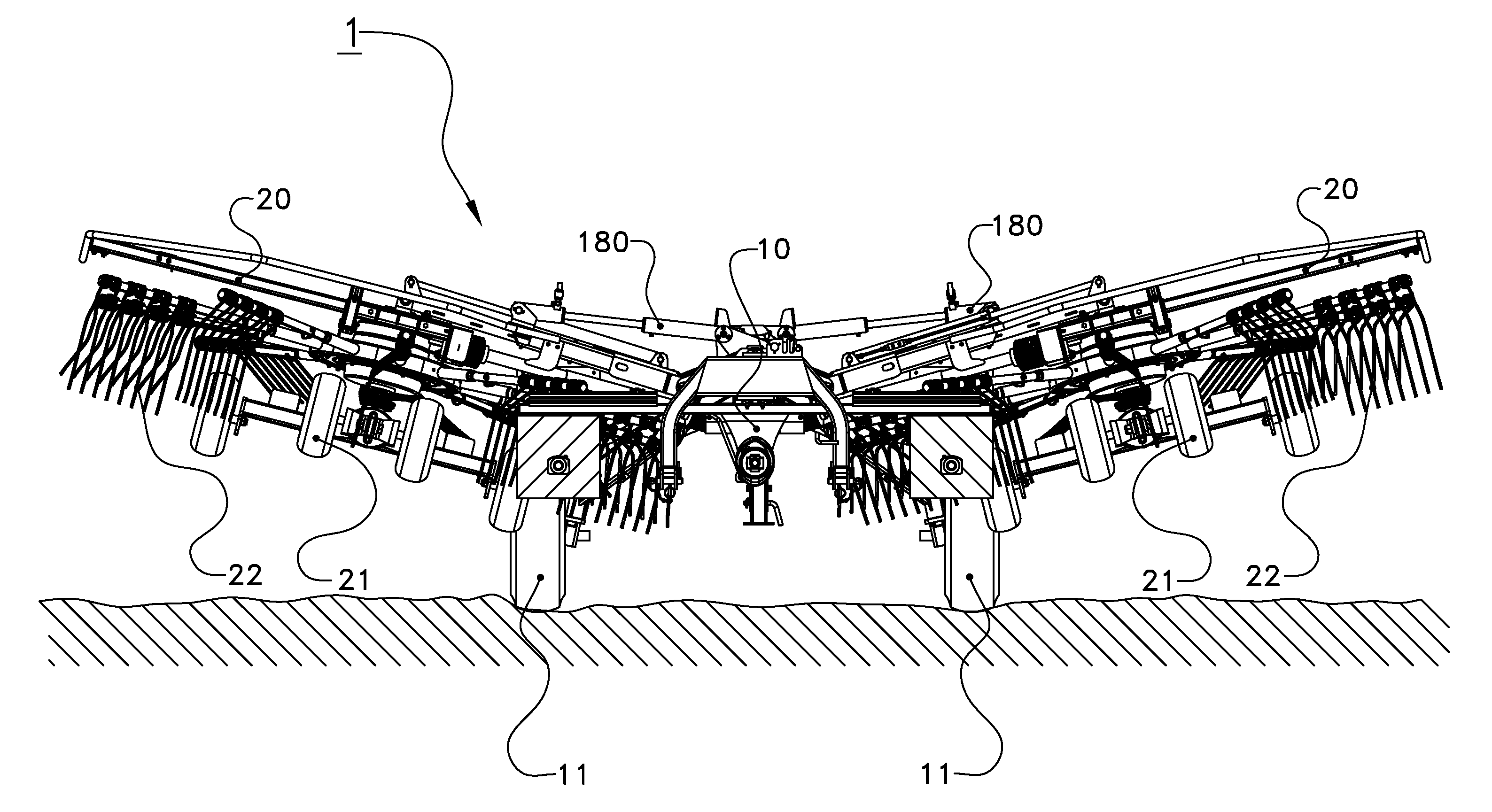
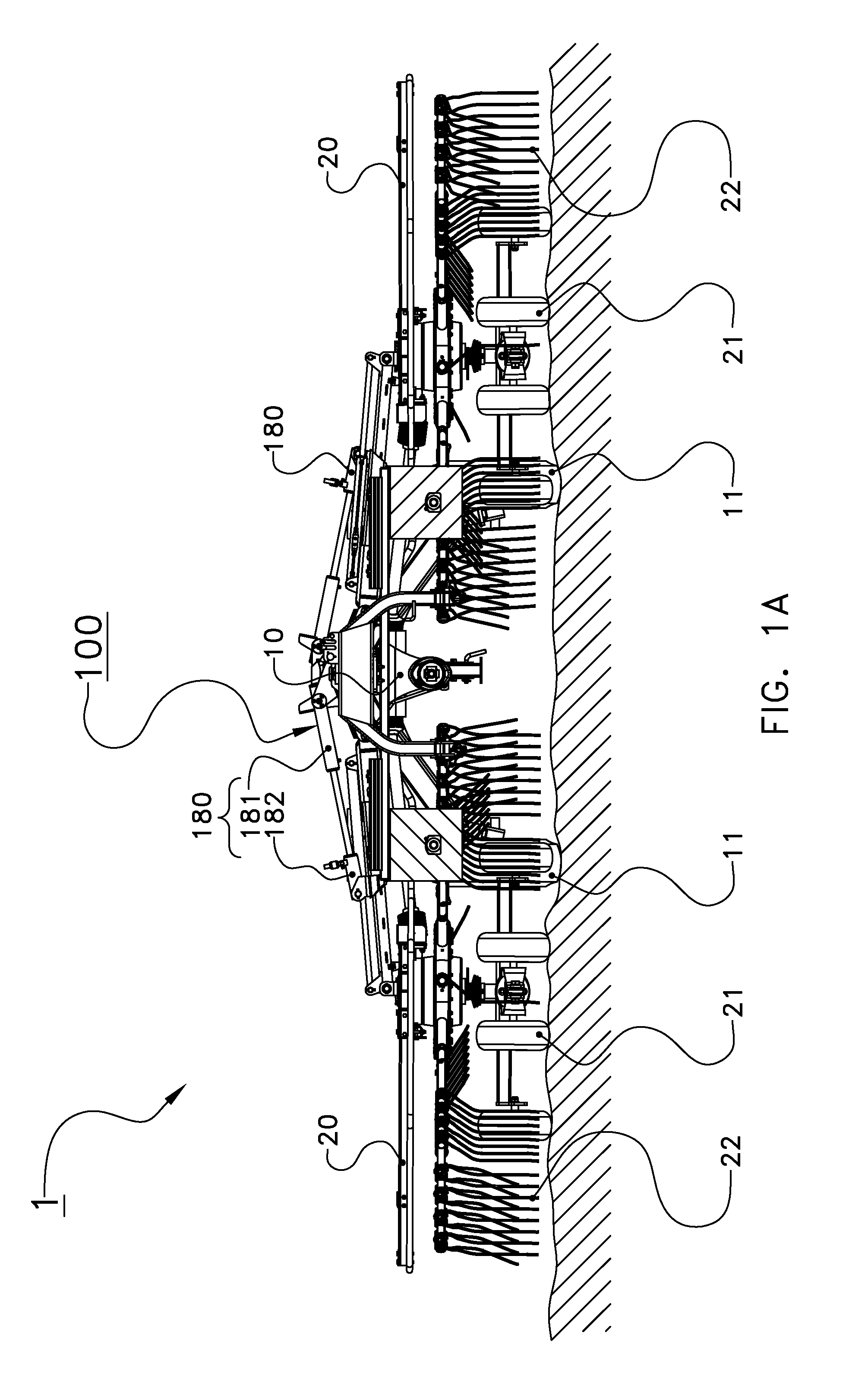
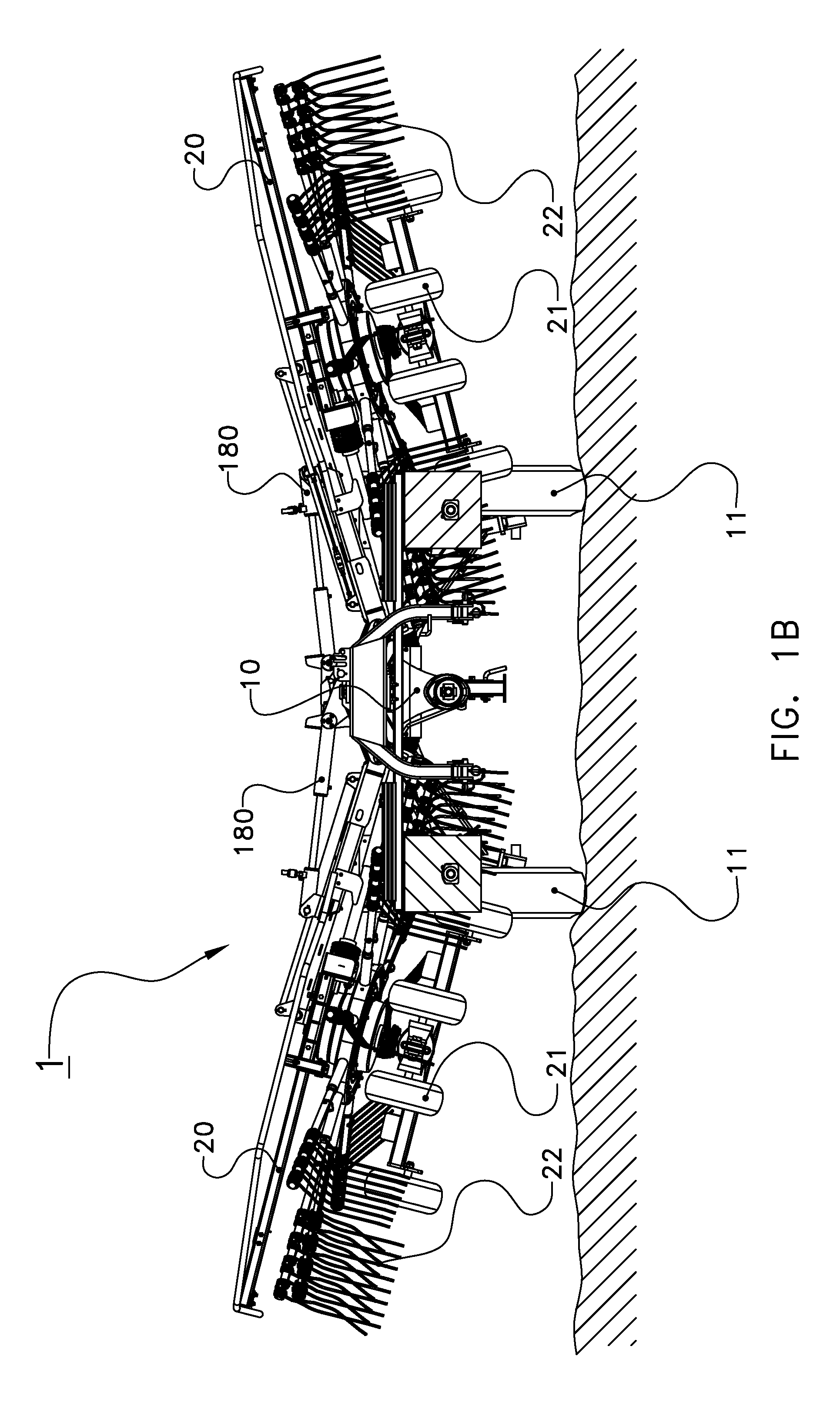
[0048]The following is a description of certain embodiments of the invention, given by way of example only and with reference to the drawings. FIGS. 1A and 1B show in a rear view an agricultural implement comprising a main frame 10 with a hingeable subframe 20 disposed on either side thereof. The main frame 10 is provided with a main wheel set 11. The subframe 20 is provided with a sub wheel set 21 and an agricultural tool 22, such as a rake member. The subframe 20 is hingeably connected to the main frame 10. In a first mode, the subframe can be kept in a low position, an operative position, as shown in FIG. 1A, in which the sub wheel set is in contact with the ground. In the low position, the agricultural tool 22 is in the operative position. The subframe can be raised to a transport position, in which the subframe is completely hinged upwardly. With inwardly folded subframes, the agricultural implement is compact for road transport. The subframe can also be hinged partially upward...


PUM


Abstract

The present invention relates to an agricultural implement with a main frame and a movable subframe connected thereto. The agricultural implement has a fluid system which comprises an accumulator which provides a suspension effect to agricultural tools connected to the agricultural implement. This provides a simple, resilient hydraulic lifting system for an agricultural implement.

Description

CROSS REFERENCE TO RELATED APPLICATIONS[0001]This application is a continuation of PCT application number PCT / NL2010 / 000168 filed on 9 Dec. 2010, which claims priority from Netherlands application number 1037612 filed on 5 Jan. 2010. Both applications are hereby incorporated by reference in their entireties.BACKGROUND OF THE INVENTION[0002]1. Field of the Invention[0003]The present invention relates to an agricultural implement with a main frame and a movable subframe connected thereto. The agricultural implement has a fluid system which comprises an accumulator which provides a suspension effect to agricultural tools connected to the agricultural implement.[0004]2. Description of the Related Art[0005]US2008 / 0093093 shows a passive hydraulic system for lowering and raising an agricultural tool. The system has cylinders for moving down and keeping down agricultural tools which are movably connected to a frame. An accumulator which is closable by means of a valve is incorporated in a ...

Claims


Application Information

Patent Timeline
Patent Type & Authority Applications(United States)
IPC IPC(8): A01B63/32
CPCA01B73/02F15B15/204F15B15/20
Inventor VAN DER LELIJ, BART
Owner LELY PATENT
Learn More