
Light emitting device and liquid crystal display device

a liquid crystal display and light-emitting technology, which is applied in the direction of optical light guides, instruments, optics, etc., can solve the problems of increasing the thickness of the liquid crystal display device, reducing the color mixing property of the laser light, and increasing the cost of the device, so as to achieve the effect of dissipating heat generated

Inactive Publication Date: 2019-04-04
SHARP KK
View PDF5 Cites 1 Cited by
  • Summary
  • Abstract
  • Description
  • Claims
  • Application Information

AI Technical Summary

Benefits of technology

The patent text describes a light emitting device that can produce uniform surface emission using a simple and efficient configuration. This device can be used in liquid crystal display devices. The technical effect of this is that it allows for more consistent and effective light emission across the entire surface of the device.

Problems solved by technology

However, in the liquid crystal display device of Non-Patent Document 1, since the laser light emitting monochromatic light of any one of red, green, and blue colors is guided to corresponding one of the light guide rods, there is a problem that color mixing property of the laser light is reduced.
In addition, in the liquid crystal display device of Non-Patent Document 1, there is another problem that, in order to realize uniform surface emission, a space / distance is desired between the light guide rods and a liquid crystal panel, which increases a thickness of the liquid crystal display device.
In addition, there is a further problem that an auxiliary member (for example, a flatter structure) for improving the color mixing property is desired, resulting in an increase in cost.
Therefore, there is a problem that the thickness, weight, and cost of the surface light source device increase and merchantability is reduced.
In addition, according to the light emitting device of Japanese Unexamined Patent Application Publication No. 2015-128011 and Japanese Unexamined Patent Application Publication No. 2016-075872, since it is difficult to align the light source and the light guide portion, there is a possibility that the efficiency of light incident on the light guide portion is deteriorated.

Method used


Image

  • Light emitting device and liquid crystal display device
  • Light emitting device and liquid crystal display device
  • Light emitting device and liquid crystal display device

Examples


embodiment 1

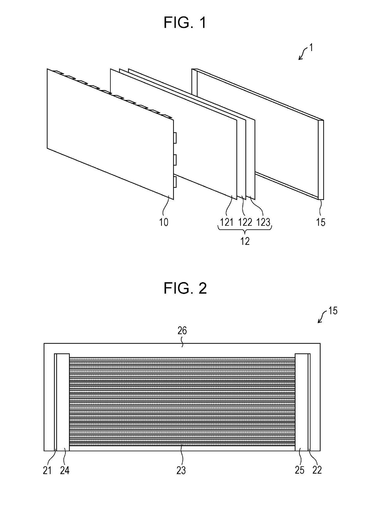
[0025]First, a liquid crystal display device including a light emitting device according to an embodiment of the present disclosure will be described with reference to FIG. 1.

[0026]Configuration of Liquid Crystal Display Device

[0027]FIG. 1 is an exploded perspective view schematically illustrating a liquid crystal display device including a light emitting device according to Embodiment 1 of the present disclosure.

[0028]As illustrated in FIG. 1, a liquid crystal display device 1 according to the present embodiment includes a liquid crystal panel 10, an optical sheet 12, and a light emitting device 15 as a backlight.

[0029]The liquid crystal panel 10 is a display panel of displaying an image, based on an input electric signal. The optical sheet 12 is provided to focus and diffuse light emitted from the light emitting device 15 and emit efficiently the light to the liquid crystal panel 10. Although the optical sheet 12 in the present embodiment includes a brightness enhancement sheet 12...

first modification example

[0062]FIGS. 7A and 7B are diagrams for explaining a first modification example of the heat sink according to the present embodiment, FIG. 7A is a perspective view schematically illustrating part of a configuration of the periphery of the heat sink, and FIG. 7B is a sectional view taken along line VIIB-VIIB illustrated in FIG. 7A.

[0063]When explaining with reference to FIGS. 7A and 7B, in a second heat sink 25a, a second light guide recess portion 43a has a shape in which a part of the periphery of the light guide rod 23 is opened. Specifically, as illustrated in FIG. 7A, the second light guide recess portion 43a holding the light guide rod 23 is formed as a U-shaped groove shape. In addition, a second light source recess portion 45a for holding the second light source unit 41 is formed in the second heat sink 25a.

[0064]According to such a configuration, the light emitted from an end surface (not illustrated) of the light guide rod 23 is not blocked by the second heat sink 25a. Ther...

second modification example

[0066]FIGS. 8A and 8B are diagrams for explaining a second modification example of the heat sink according to the present embodiment, FIG. 8A is a perspective view schematically illustrating part of a configuration of the periphery of the heat sink, and FIG. 8B is a sectional view taken along line VIIIB-VIIIB illustrated in 8A.

[0067]When explaining with reference to FIGS. 8A and 8B, in a second heat sink 25b, a second light guide recess portion 43b is formed as the U-shaped groove shape in which a part of the periphery of the light guide rod 23 is opened, similar to the heat sink 25a (see FIGS. 7A and 7B) according to the above-described first modification example. In addition, a second light source recess portion 45b for holding the second light source unit 41 is formed in the heat sink 25b. Furthermore, a stopper 431a is formed on an inner side surface of a U-shaped groove of the second light guide recess portion 43b. Furthermore, a protrusion portion 432b surrounding part of an o...


PUM

PropertyMeasurementUnit
diameteraaaaaaaaaa
diameteraaaaaaaaaa
refractive indexaaaaaaaaaa

Abstract

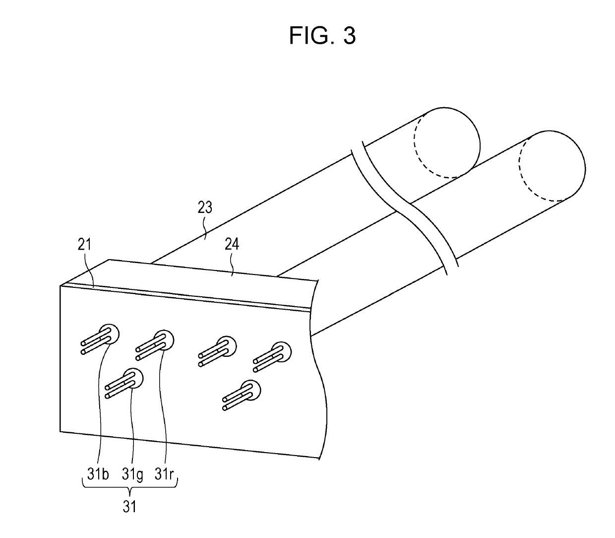
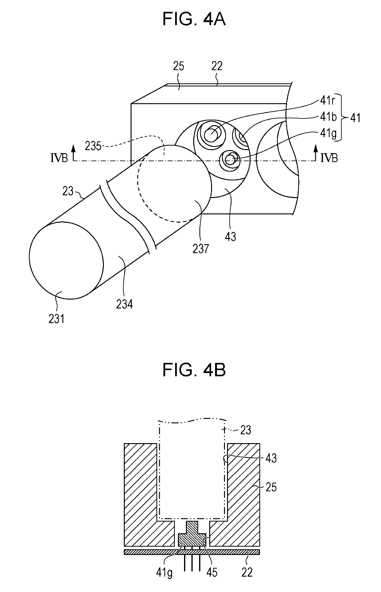
A light emitting device includes a first light source unit and a second light source unit that emit three or more types of laser light beams having wavelengths different from each other, a light guide portion in which the laser light beams emitted from both the first light source unit and the second light source unit are guided, and a first heat sink and a second heat sink that respectively hold the first light source unit and the second light source unit at predetermined positions, and dissipate heat generated from the first light source unit and the second light source unit.

Description

BACKGROUND1. Field[0001]The present disclosure relates to a light emitting device and a liquid crystal display device including the light emitting device.2. Description of the Related Art[0002]So far, various liquid crystal display devices such as a liquid crystal TV are developed. For example, in Eiji Niikura, “An RGB laser-backlit liquid crystal display”, ITU Journal Vol. 46 No. 2 (2016, 2), pp. 32-35 (hereinafter referred to as Non-Patent Document 1), a liquid crystal display device is disclosed. In the liquid crystal display device, a surface light source is implemented by alternately arranging a laser diode of emitting red (R) light, a laser diode of emitting green (G) light, and a laser diode of emitting blue (B) light on the left and right in a longitudinal direction of the liquid crystal display device and by arranging a light guide rod for each laser diode.[0003]In addition, in Japanese Unexamined Patent Application Publication No. 2017-091984, a surface light emitting devi...

Claims


Application Information

Patent Timeline
Patent Type & Authority Applications(United States)
IPC IPC(8): F21V8/00G02F1/13357
CPCG02B6/001G02F1/1336G02F2001/133628G02F1/133621G02B6/0085G02B6/0068G02F1/133628
Inventor KITAMURA, HIROSHIFUJII, HIDEKAZUMURAKOSHI, KENICHIAGATANI, MAKOTO
Owner SHARP KK
Learn More