
Medical instrument

a technology of medical instruments and guide wires, applied in the field of medical instruments, can solve the problems of deteriorating function, complicated configuration of the tip of the catheter or guide wire, etc., and achieve the effect of simple and efficient configuration

Inactive Publication Date: 2017-10-05
NIPPON PISTONRING CO LTD
View PDF4 Cites 1 Cited by
  • Summary
  • Abstract
  • Description
  • Claims
  • Application Information

AI Technical Summary

Benefits of technology

The medical instrument described in this patent is designed to have a simple and efficient configuration. This means that it is designed to be easy and straightforward to use.

Problems solved by technology

A marker is further added to such structures, resulting in the complicated configuration of the tip of the catheter or guide wire.
Depending on the configuration of the tip, the marker may have a difficulty in being disposed at an appropriate position, or the provision of the marker may deteriorate the function that should have been exerted by the catheter or the guide wire.

Method used


Image

  • Medical instrument
  • Medical instrument
  • Medical instrument

Examples


Embodiment Construction

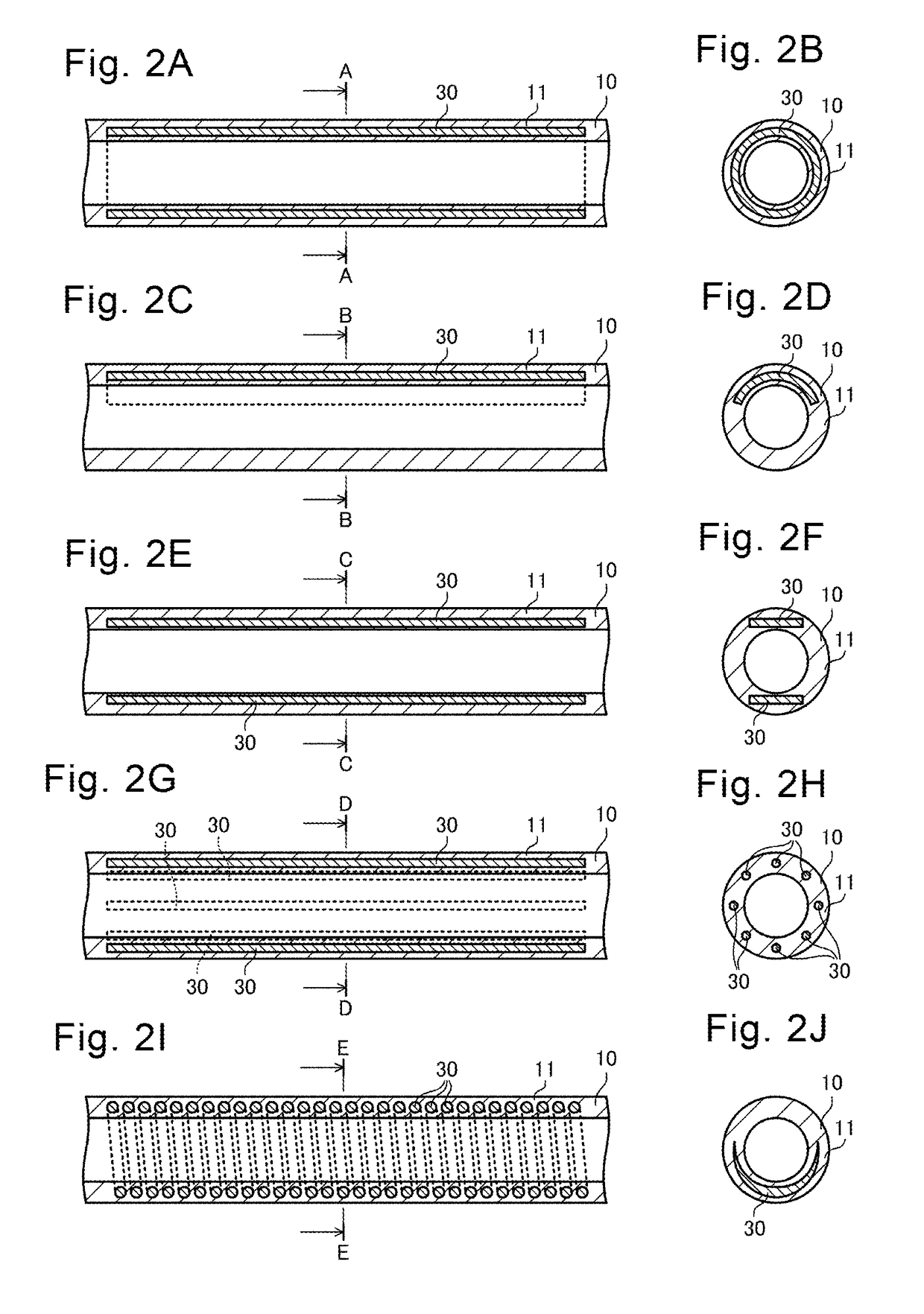
[0048]An embodiment of the present invention will now be described below with reference to the accompanying drawings. Note that the drawings include unshown or simplified parts for ease of comprehension. Note also that the shapes or dimension ratios of elements in the drawings are not necessarily accurate.

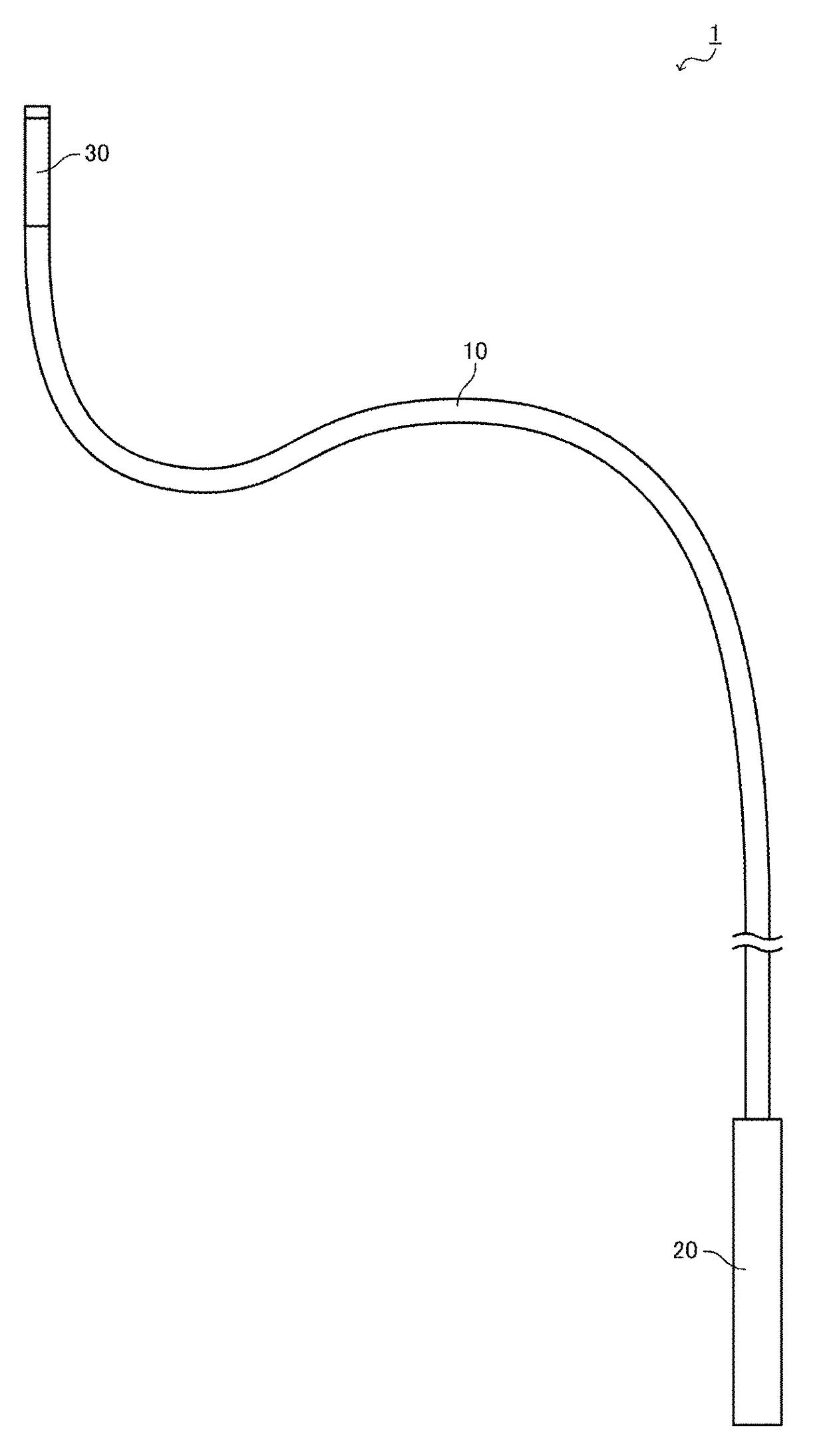
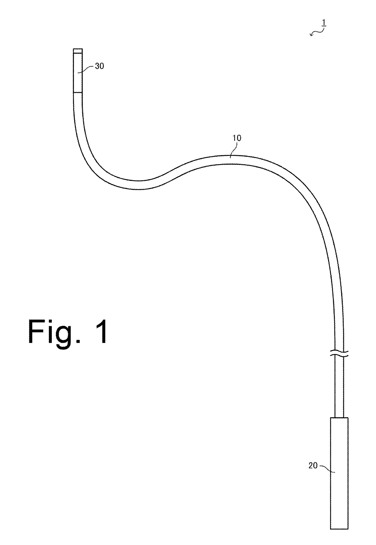
[0049]FIG. 1 is a schematic diagram showing a medical instrument 1 of the present embodiment. At least a part of the medical instrument 1 is inserted into a tubular organ such as a blood vessel, the ureter, the bile duct, the trachea, and the intestine in a living body such as a human body to perform various procedures such as examinations, diagnoses, and treatment. As shown in FIG. 1, the medical instrument 1 includes: an elongated part 10, at least a part of which is inserted into a living body; an operation part 20 provided on the hand side of the elongated part 10; and an alloy part 30 provided on the tip side of the elongated part 10.

[0050]The elongated part 10 is an elongated...


PUM

PropertyMeasurementUnit
strengthaaaaaaaaaa
axial rigidityaaaaaaaaaa
bending rigidityaaaaaaaaaa

Abstract

There is provided a medical instrument achieving a simple and efficient configuration. The medical instrument includes: an elongated part formed in a linear or tubular shape, at least a part of which is inserted into a living body; and an alloy part provided in the elongated part and formed from an alloy containing titanium and tantalum.

Description

BACKGROUND OF THE INVENTION1. Field of the Invention[0001]The present invention relates to a medical instrument, at least a part of which is inserted into a living body, such as a catheter or a guide wire.2. Description of the Related Art[0002]In the medical field, various procedures have been conventionally performed by inserting a catheter having a tubular body or a guide wire having a linear body into various tubular organs of a living body. In a procedure of dilating a stenosis site in a blood vessel, for example, a flexible guide wire is first inserted into the blood vessel until the tip thereof reaches the target stenosis site. Subsequently, a balloon catheter having a balloon at its tip is inserted into the blood vessel along the guide wire until the balloon reaches the stenosis site. Thereafter, a fluid such as air is introduced into the balloon to inflate the balloon. In this manner, the stenosis site is dilated.[0003]Such a procedure is typically performed while a radiogra...

Claims


Application Information

Patent Timeline
Patent Type & Authority Applications(United States)
IPC IPC(8): A61B18/14
CPCA61B18/1492A61B2018/00577A61B18/1477A61B2018/1407A61B2018/144A61B2018/141A61B18/1445A61B2090/3966A61B2018/00267C22C14/00C22C27/02A61L31/022
Inventor ISHIKAWA, YOSHIKIKUBO, TAKASUMIKIMURA, YUKIMATSUSHIMA, HIROSHI
Owner NIPPON PISTONRING CO LTD
Learn More