
Steering column support apparatus

a support apparatus and steering column technology, applied in the direction of steering columns, steering parts, vehicle components, etc., can solve the problems of reducing the stability of the steering column, so as to simplify the tuning of the forward displacement of the steering wheel, prevent the steering wheel from dropping excessively, and simplify the effect of stabilizing the steering wheel

Inactive Publication Date: 2012-10-25
NSK LTD
View PDF0 Cites 22 Cited by
  • Summary
  • Abstract
  • Description
  • Claims
  • Application Information

AI Technical Summary

Benefits of technology

[0054]With the steering column support apparatus of the present invention, construction is achieved in which it is possible to simplify tuning for stabilizing the forward displacement of the steering wheel during a secondary collision, lower and stabilize the break away load, and when necessary, prevent the steering wheel from dropping excessively during a secondary collision.
[0055]Simplifying the tuning for stabilizing the forward displacement of the steering wheel during a secondary collision is made possible by engaging the bracket on the vehicle side and bracket on the column side in the portion between two locations on both sides where the bracket on the vehicle side is fastened to the vehicle side. Through engagement in the portion between these two locations in the width direction (middle section in the width direction), impact that is applied to the bracket on the column side during a secondary collision is applied nearly uniformly at the engagement section between the bracket on the vehicle side and the bracket on the column side, and because it becomes difficult for a moment in the bending direction to be applied to the bracket on the column side, it becomes possible to simplify tuning.
[0056]Lowering and stabilizing the break away load, in the first aspect of the present invention, is made possible by holding the bracket on the vehicle side and the bracket on the column side between part of a pair of top and bottom sliding plate sections of a sliding member located in part of the bracket on the vehicle side. With the existence of these sliding plate sections, it is possible to keep the friction force acting between both the top and bottom surfaces of the bracket on the vehicle side and the bottom surface of the restraining portion and the top surface of the top plate section of the bracket on the column side. Therefore, it is possible to lower and stabilize the break away load that is determined based on this friction force.
[0057]In the second aspect of the present invention, a pressure plate section on the bottom side is provided on the bracket on the vehicle side, a pressure plate section on the top side is provided on the bracket on the column side, and the bracket on the vehicle side and the bracket on the column side are connected by the friction force that occurs when at least one of these pressure plates section pushes the opposing side, and the friction force that occurs by holding the portions on both the left and right sides of the locking cutout section in the bracket on the vehicle side between the top plate section of the bracket on the column side and a restraining plate that is connected to the top plate section by a fastening member. Of these friction forces, the friction force that occurs by holding the portions on both the left and right sides of the locking cutout section between the top plate section and the restraining plate can easily be adjusted by the connecting force of the fastening member (force acting in the axial direction of the fastening member). Therefore, it is possible to lower and stabilize the break away load, which is the total of these friction forces.
[0058]Preventing the steering wheel from dropping (falling) excessively during a secondary collision is achieved by making the length in the forward / backward direction of the locking cutout section sufficiently long. With this construction, even when the steering wheel has displaced completely in the forward direction as the secondary collision advanced, it is possible to prevent the restraining portion of the fastening member or bottom surface of the restraining plate from becoming disengaged from the top surface of the front end section of the bracket on the vehicle side, and to prevent the edge on the front end of the locking cutout section from hitting against the fastening member. Therefore, downward displacement of the bracket on the column side with respect to the bracket on the vehicle side is prevented, so it is possible to prevent the steering wheel, which is supported by the bracket on the column side by way of the steering column, from dropping excessively. As a result, depending on the extent of the collision accident, it is possible to maintain operability of the steering wheel, making it easier to perform the work of moving the vehicle that was in the accident out of the way, such as to the side of the road.

Problems solved by technology

In order to shear these locking pins, a certain amount of the impact load is required, that is disadvantage for suppressing the break away load.
On the other hand, in the construction shown in FIG. 42 to FIG. 44, tuning in order to stabilize the attitude of steering column 6a takes time and trouble, and a slight change in tightening torque of a bolt or the like for assembling the bracket 12 on the column side on the vehicle body side causes the break away load to vary widely, complicating the control of the tightening torque.

Method used


Image

  • Steering column support apparatus
  • Steering column support apparatus
  • Steering column support apparatus

Examples


embodiment 1 , example 1

Embodiment 1, Example 1

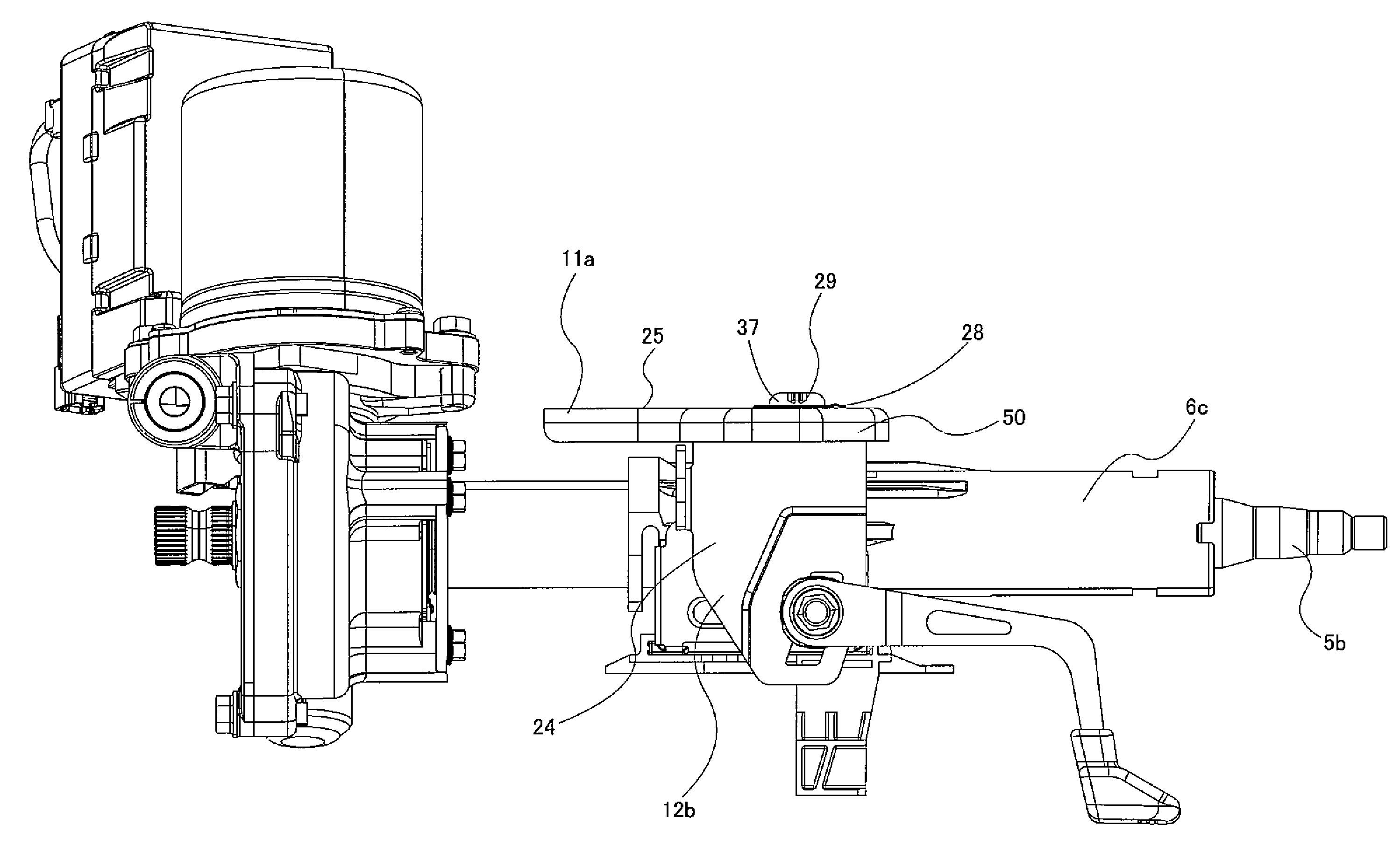
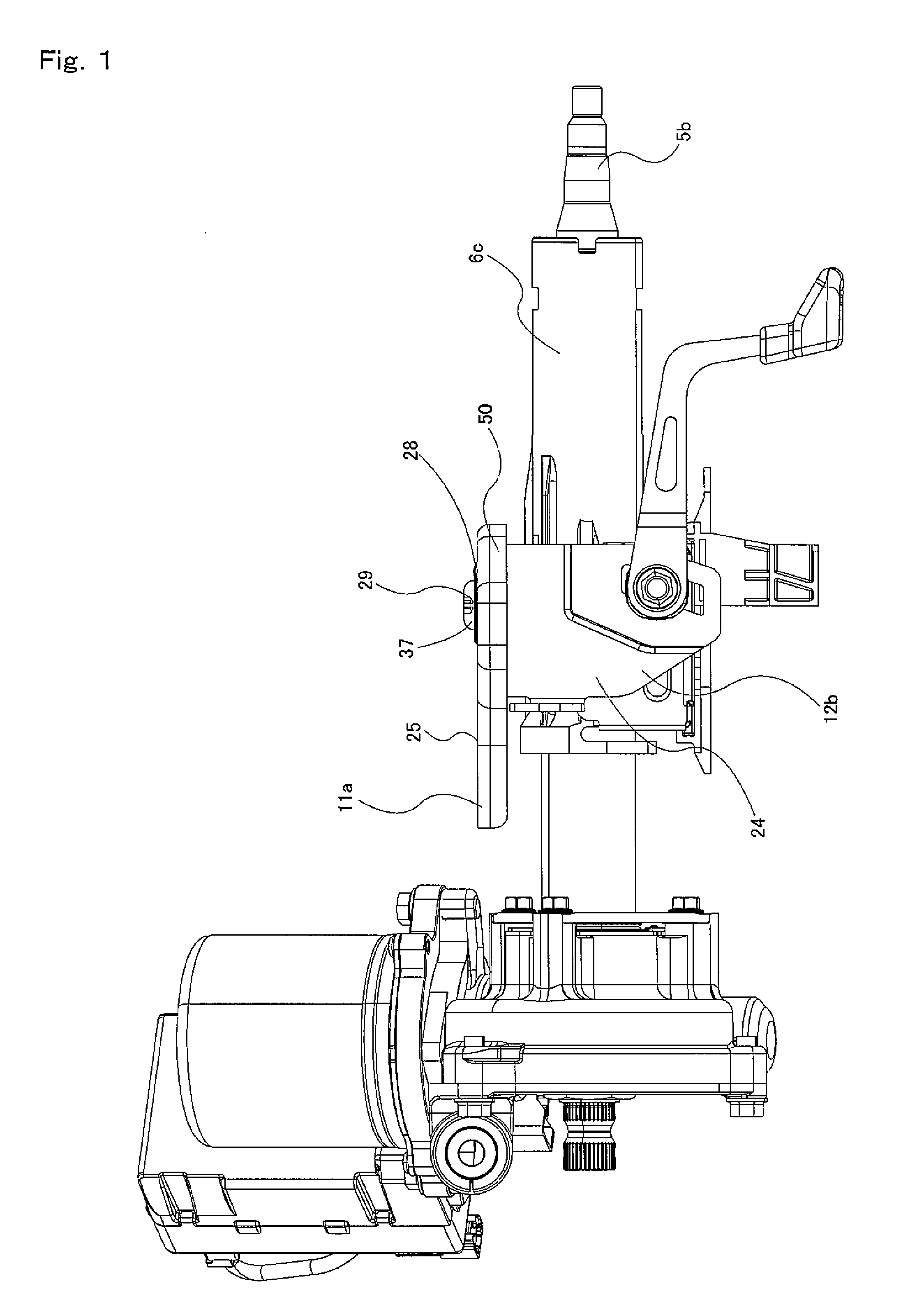
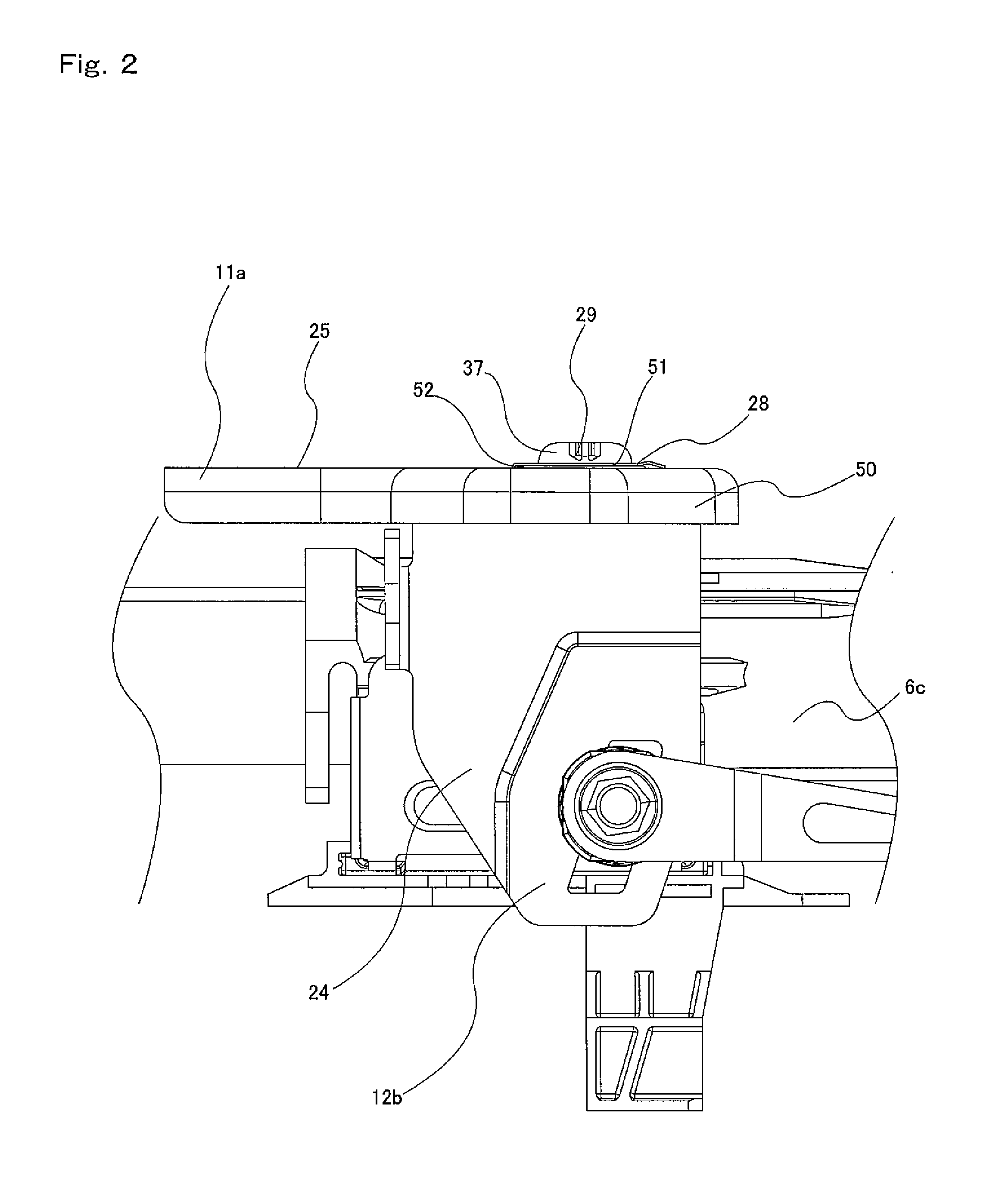
[0106]FIG. 1 to FIG. 6 illustrate a first example of a first embodiment of the present invention. The steering support apparatus to which the present invention is applied, basically comprises: a bracket 11a on the vehicle side that is made of metal, is fastened to the vehicle body in at least two locations on both sides in the width direction, does not displace in the forward direction during a secondary collision, and has a locking cutout section that is located between the two locations on both sides in the width direction and that extends in the forward / backward direction; and a bracket 12b on the column side that is made of metal, is located on the underneath side of the bracket 11a on the vehicle side, supports the steering column and has a top plate section 23 on the top end section that has a width dimension that is greater than the width dimension of the locking cutout section. A feature of the present invention is the construction for supporting the b...

embodiment 1 , example 2

Embodiment 1, Example 2

[0120]FIG. 7 and FIG. 8 illustrate a second example of the first embodiment of the present invention. In this example, a rectangular reinforcing plate 38 that is long in the left to right width direction is provided on the top side of the pair of sliding members 28, and spans between these sliding members 28. The top surface of the reinforcing plate 38 is pressed downward toward the base plate section 25 of the bracket 11a on the vehicle side by the head sections 37 of the pair of left and right bolts 29.

[0121]In the construction of this example, it is possible to stabilized the top surfaces of the sliding members 28, and further stabilize the connecting force between the bracket 11a on the vehicle side and the bracket 12b on the column side. It is also possible to alternatively or additionally stabilize the tightening force of the bolts 29 and nuts 30 even though separate washers may be used, so it is possible to further stabilize the break away load. The con...

embodiment 1 , example 3

Embodiment 1, Example 3

[0122]FIG. 9 illustrates a third example of the first embodiment of the present invention. In this example, auxiliary sliding plates 39 are held between the bottom surface of the reinforcing plate 38 and the top surfaces of the sliding plate sections 31a on the top side of the sliding members 28, and between the top surface of the top plate section 23 of the bracket 12b on the column side and the bottom surfaces of the sliding plate sections 31a on the bottom side of the sliding members 28. The surfaces of these auxiliary sliding plates 39 that face the top or bottom surfaces of the sliding members 28 are coated with a coating layer made of a low-friction material such as polytetrafluoroethylene resin, polyamide resin, molybdenum disulfide and the like.

[0123]In the case of the construction of this example, sliding occurs between coating layers made of low-friction material during a secondary collision, so it is possible to further lower and stabilize the break...


PUM


Abstract

Construction of a steering column support apparatus is achieved that simplifies tuning for stabilizing forward displacement of a steering wheel during a secondary collision, lowers and stabilizes the break away load, and when necessary, prevents the steering wheel from dropping excessively after a secondary collision. A locking cutout section 27 that extends in the forward / backward direction is formed in a bracket 11a on the vehicle side, top and bottom sliding plate sections 31a, 31b that are formed on outside and inside sliding plates 51, 52 of a sliding member 28 are located on both the top and bottom surfaces of the portions on both sides of the locking cutout section 27. A bolt that is inserted from the top through these sliding plate sections 31a, 31b and a nut 30 connect the top plate section 23 of a bracket 12b on the column side to the bracket 11a on the vehicle side. During a secondary collision, the outside sliding plate 51 slides and moves in the forward direction with respect to the inside sliding plate 52, and the bracket 12b on the column side breaks away from the bracket 11a on the vehicle side with little force.

Description

FIELD OF THE INVENTION[0001]The present invention relates to a steering column support apparatus that supports a steering column such that the steering column can displace in the forward direction with respect to the vehicle body in order to enable the steering wheel to displace in the forward direction while absorbing impact energy that is applied to the steering wheel from the body of the driver during an impact collision.BACKGROUND ART[0002]A steering apparatus for an automobile, as illustrated in FIG. 41, is constructed so that rotation of the steering wheel 1 is transmitted to an input shaft 3 of a steering gear unit 2, and as this input shaft 3 turns, the input shaft 3 pushes or pulls a pair of left and right tie rods 4, which apply a steering angle to the front wheels of the automobile. The steering wheel 1 is fastened to and supported by the rear end section of a steering shaft 5, and this steering shaft 5 is inserted in the axial direction through a cylindrical shaped steer...

Claims


Application Information

Patent Timeline
Patent Type & Authority Applications(United States)
IPC IPC(8): B62D1/19
CPCB62D1/195
Inventor FUJIWARA, TAKESHISADAKATA, KIYOSHISEGAWA, TORUMINAMIGATA, TAKAHIRO
Owner NSK LTD
Learn More