Exposure apparatus and image forming apparatus

Active Publication Date: 2012-10-25
CANON KK
View PDF3 Cites 7 Cited by
  • Summary
  • Abstract
  • Description
  • Claims
  • Application Information

AI Technical Summary

Benefits of technology

[0007]The present invention has been made in consideration of the above-mentioned problem, and provides a technique to reduce a potential erro

Problems solved by technology

This unevenness of sensitivity may occur due to the difficulty in maintaining the thickness of a photosensitive layer of a photosensitive member constant in a process of manufacturing the photosensitive member.
As a result, potential unevenness (error) may occur in this surface potential.
Therefore, if unevenness occurs in the potential characteristics of the surface of the photosensitive member, density unevenness may occur in the formed image upon development of the electrostatic latent image using a developing material such as toner.
Especially when the drive current is modulated (by, for

Method used


Image

  • Exposure apparatus and image forming apparatus
  • Exposure apparatus and image forming apparatus
  • Exposure apparatus and image forming apparatus

Examples


Example

First Embodiment

1>

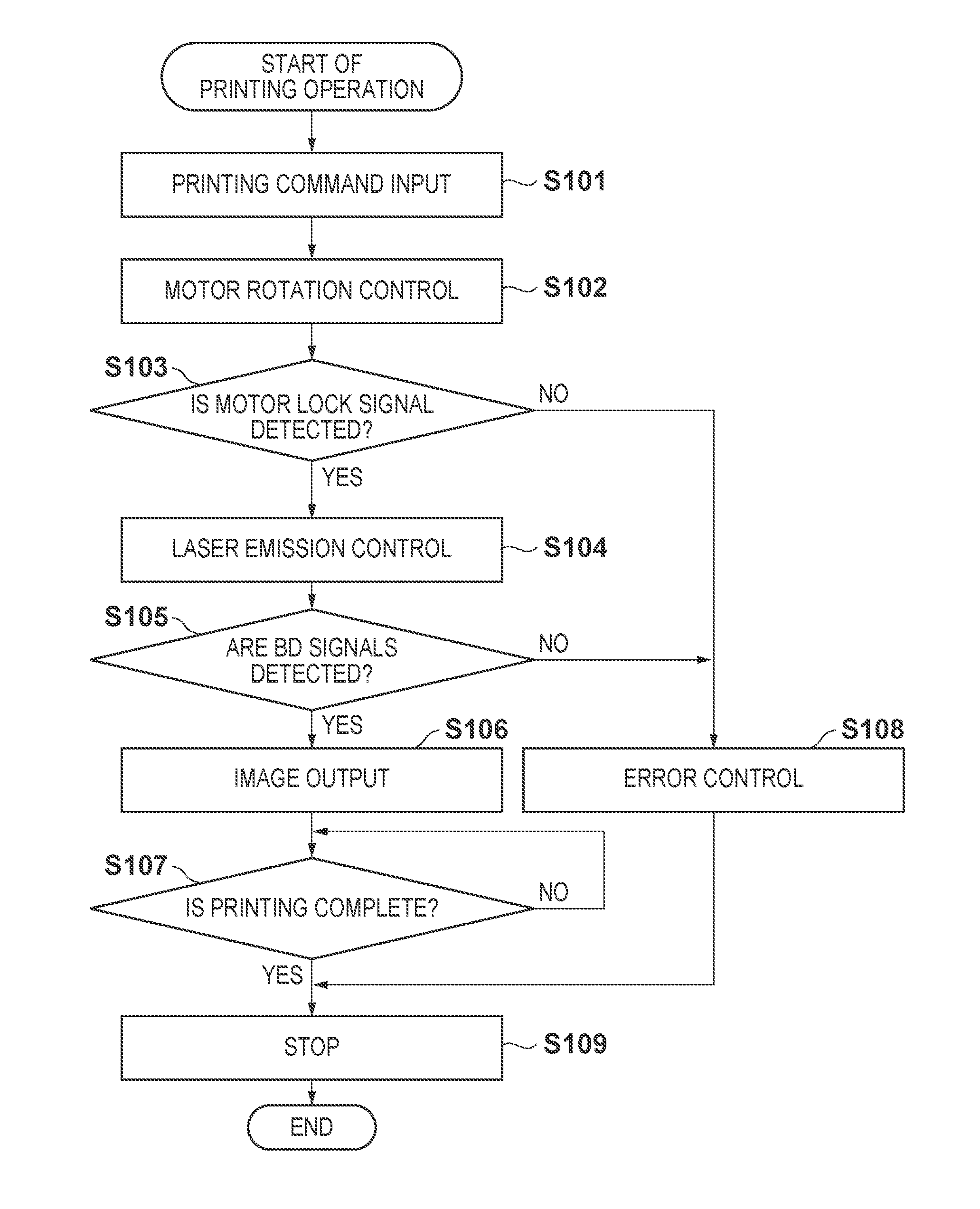
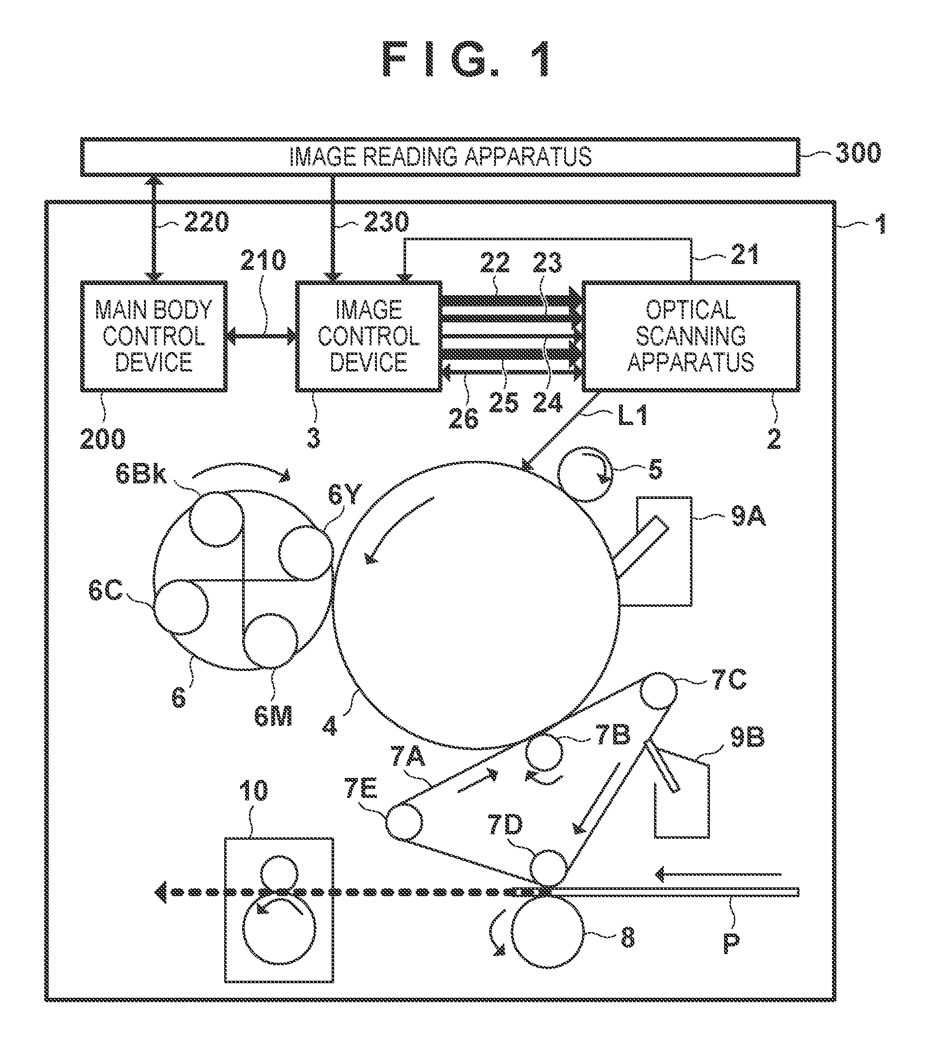
[0025]The configuration of an image forming apparatus 1 according to the first embodiment of the present invention will be described first with reference to FIG. 1. The image forming apparatus 1 executes an image forming process of forming an image on the surface of a transfer material (printing material) P based on input image information. The image information may be input from an image reading apparatus 300 or input via a network from other external apparatuses such as an information processing apparatus (computer). The image forming process includes a charging process, exposure process, developing process, transfer process, and fixing process to be described hereinafter. The image forming apparatus 1 sequentially executes these processes to form an image on the surface of the transfer material P.

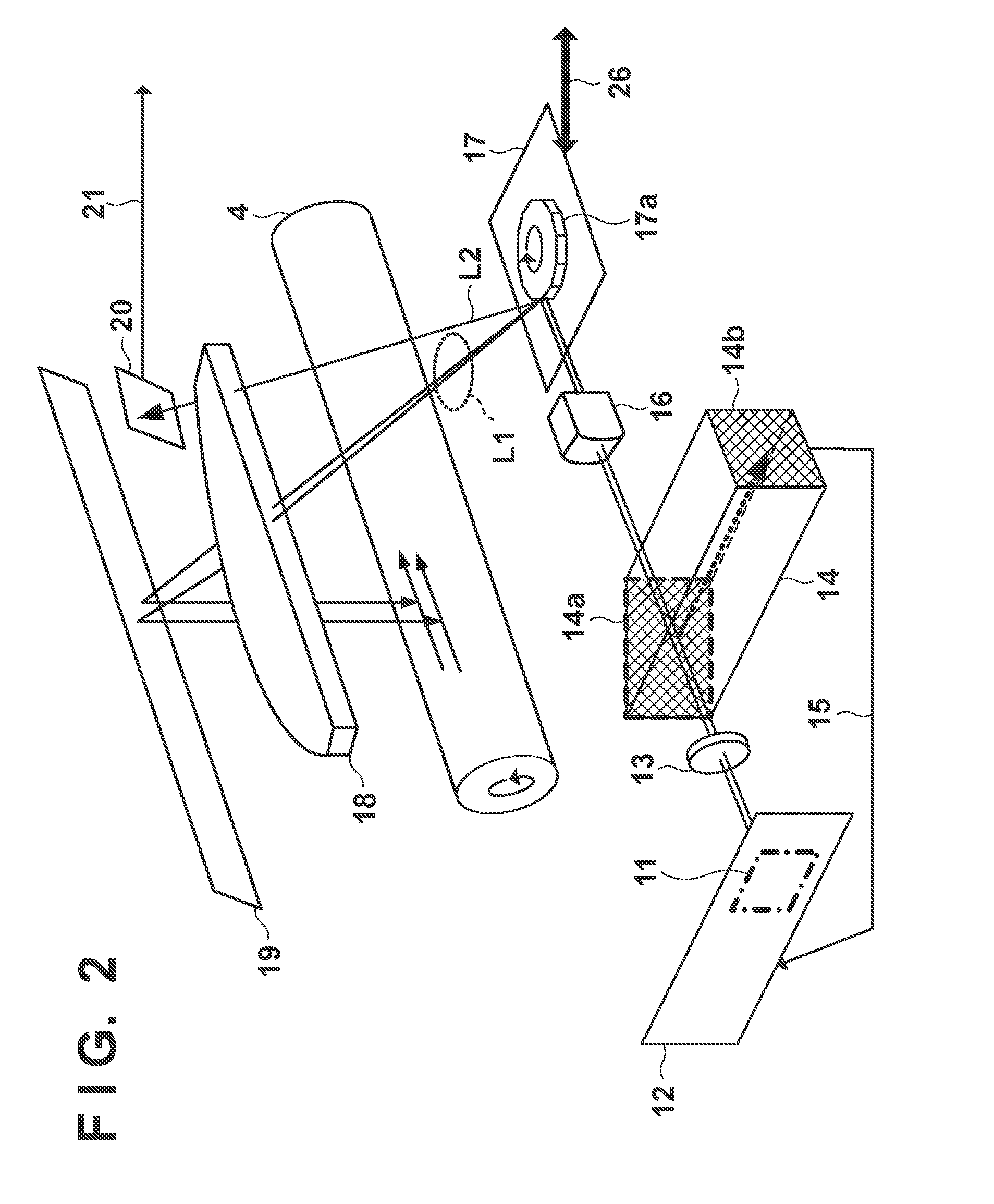
[0026]The image forming apparatus 1 includes a drum-shaped photosensitive drum 4 which rotates in a direction indicated by an arrow in FIG. 1 as an example of the photo...


PUM


Abstract

An exposure apparatus according to this invention uses both a first light source which outputs a light beam corresponding to a drive current corresponding to image information, and a second light source to irradiate the surface of a photosensitive drum with a plurality of light beams. The second laser light source irradiates the photosensitive drum with a laser beam in accordance with a drive current corresponding to a correction value according to which unevenness of potential characteristics due to unevenness of sensitivity of the surface of the photosensitive drum is reduced. The same region on the surface of the photosensitive drum is irradiated with laser beams which are output from the first and second laser light sources onto the photosensitive drum in superposition.

Description

BACKGROUND OF THE INVENTION[0001]1. Field of the Invention[0002]The present invention relates to an exposure apparatus and an image forming apparatus using the same.[0003]2. Description of the Related Art[0004]An electrophotographic image forming apparatus generally exposes the surface of a photosensitive member to a light beam (laser beam) output from a light source (laser light source) provided in an exposure apparatus such as an optical scanning apparatus, thereby forming an electrostatic latent image on the surface of the photosensitive member. The photosensitive member on which an electrostatic latent image is formed may have a sensitivity which varies in each individual position (region), that is, unevenness of sensitivity on its surface. This unevenness of sensitivity may occur due to the difficulty in maintaining the thickness of a photosensitive layer of a photosensitive member constant in a process of manufacturing the photosensitive member. When the photosensitive member ...

Claims


Application Information

Patent Timeline
IPC IPC(8): G03B27/54
CPCG03G15/043H04N1/1135H04N2201/0082H04N1/191H04N1/12
Inventor SEKI, YUICHI
Owner CANON KK
Why Eureka
Try Eureka