Heat dissipation unit for LED bulb

Inactive Publication Date: 2012-10-25
LEE YEN CHING +1
View PDF3 Cites 12 Cited by
  • Summary
  • Abstract
  • Description
  • Claims
  • Application Information

AI Technical Summary

Benefits of technology

[0011]The second heat dissipation member is formed with a second through hole in communication with the perforation and a spreading section extending from the second through hole. The second side of the heat dissipation section is attached to the spreading section. The retainer member is fitted in

Problems solved by technology

Recently, the problem of global warming has become more and more serious.
Therefore, the luminous efficiency of the conventional incandescent bulb is very low and a great amount of energy is wasted.
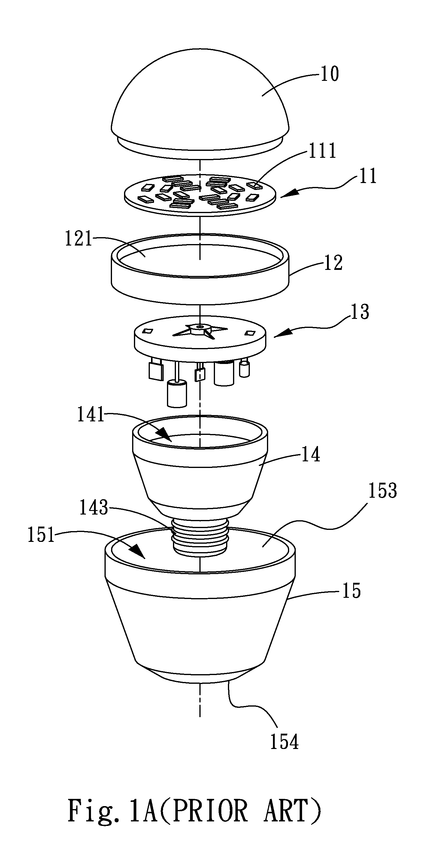
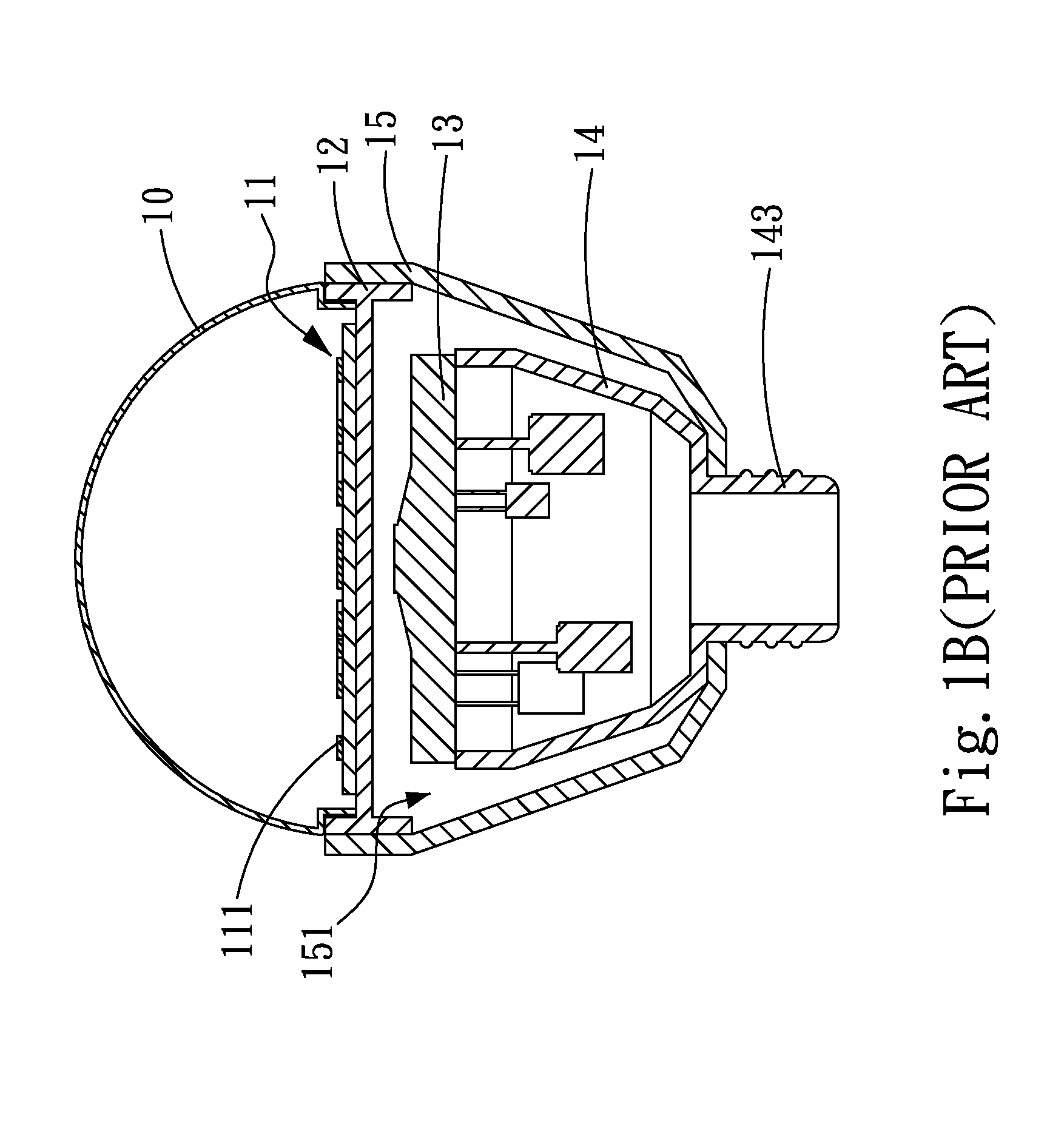
This may lead to damage to the LED chips 111

Method used


Image

  • Heat dissipation unit for LED bulb
  • Heat dissipation unit for LED bulb
  • Heat dissipation unit for LED bulb

Examples


Example

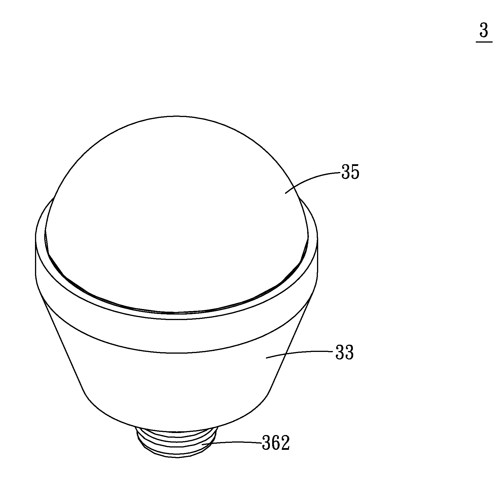
[0026]Please refer to FIGS. 2A, 2B and 3. According to a first embodiment, the heat dissipation unit 2 for light-emitting diode (LED) bulb of the present invention includes a base seat 21, a first heat dissipation member 22, a second heat dissipation member 24 and a retainer member 25. The base seat 21 is formed with a receiving cavity 210 and a base section 213. The receiving cavity 210 has an open end 211, a closed end 212 opposite to the open end 211 and a first through hole 214. The open end 211 and the closed end 212 together define the receiving cavity 210. The first through hole 214 is formed at a center of the closed end 212 in communication with the receiving cavity 210. The base seat 21 and the first and second heat dissipation members 22, 24 are made of metal material (such as aluminum, copper and an alloy).

[0027]The first heat dissipation member 22 has multiple heat dissipation sections 221 and a perforation 223 in alignment with and in communication with the first throu...

Example

[0034]Please now refer to FIGS. 4C and 6A, which show a second embodiment of the present invention. In the second embodiment, the base seat 21 is further formed with multiple first vents 216 passing through the closed end 212 of the receiving cavity 210 and the base section 213. The first vents 216 are respectively positioned on two sides of the corresponding LEDs 311. That is, as shown in FIG. 4C, two first vents 216 are formed on two sides of a section of the closed end 212, which section is right under each LED 311. The first vents 216 help to quickly transfer the heat of the LEDs 311 to the first heat dissipation member 22 for dissipating the heat.

Example

[0035]Please now refer to FIGS. 4D and 6B, which show a third embodiment of the present invention. In the third embodiment, the base seat 21 is further formed with multiple first vents 216. The first vents 216 of the third embodiment are identical to those of the second embodiment in structure and function and thus will not be repeatedly described hereinafter. In the third embodiment, the second heat dissipation member 24 is further formed with multiple second vents 217 passing through the spreading section 242 corresponding to the first vents 216.


PUM


Abstract

A heat dissipation unit for LED bulb includes a base seat formed with a receiving cavity and a base section, a first heat dissipation member having multiple heat dissipation sections and a perforation, a second heat dissipation member and a retainer member. The heat dissipation sections of the first heat dissipation section are arranged around the perforation. Each heat dissipation section has a first side attached to the base section and a second side. A first through hole is formed in the receiving cavity in communication with the receiving cavity and the perforation. The second heat dissipation member is formed with a second through hole and a spreading section attached to the second side of the heat dissipation section. The retainer member is fitted in the first and second through holes and the perforation to integrally connect the base seat with the first and second heat dissipation members.

Description

FIELD OF THE INVENTION[0001]The present invention relates generally to a heat dissipation unit for LED bulb, and more particularly to a heat dissipation unit, which can provide excellent heat dissipation effect for an LED bulb to enhance luminous efficiency of the LED bulb.BACKGROUND OF THE INVENTION[0002]Recently, the problem of global warming has become more and more serious. Therefore, various green products meeting the requirements of energy saving and carbon reduction have been more and more respected. As for light bulbs, when a conventional incandescent bulb emits light, 90% of the energy is converted into thermal energy, while only 10% of the energy becomes light. Therefore, the luminous efficiency of the conventional incandescent bulb is very low and a great amount of energy is wasted.[0003]Lately, for eliminating the above shortcoming of the conventional incandescent bulbs, various light-emitting devices such as light-emitting diode (LED) bulbs have been developed to substi...

Claims


Application Information

Patent Timeline
IPC IPC(8): F21V29/00F21S4/00
CPCF21V29/004F21Y2101/02F21Y2105/001F21V3/00F21V29/89F21V23/006F21V29/713F21V29/773F21V29/83F21K9/135F21Y2105/10F21K9/232F21Y2115/10F21K9/238
Inventor LEE, WEN-JEN
Owner LEE YEN CHING
Why Eureka
Try Eureka