
Container refrigeration apparatus

Active Publication Date: 2012-11-01
DAIKIN IND LTD
View PDF5 Cites 20 Cited by
  • Summary
  • Abstract
  • Description
  • Claims
  • Application Information

AI Technical Summary

Benefits of technology

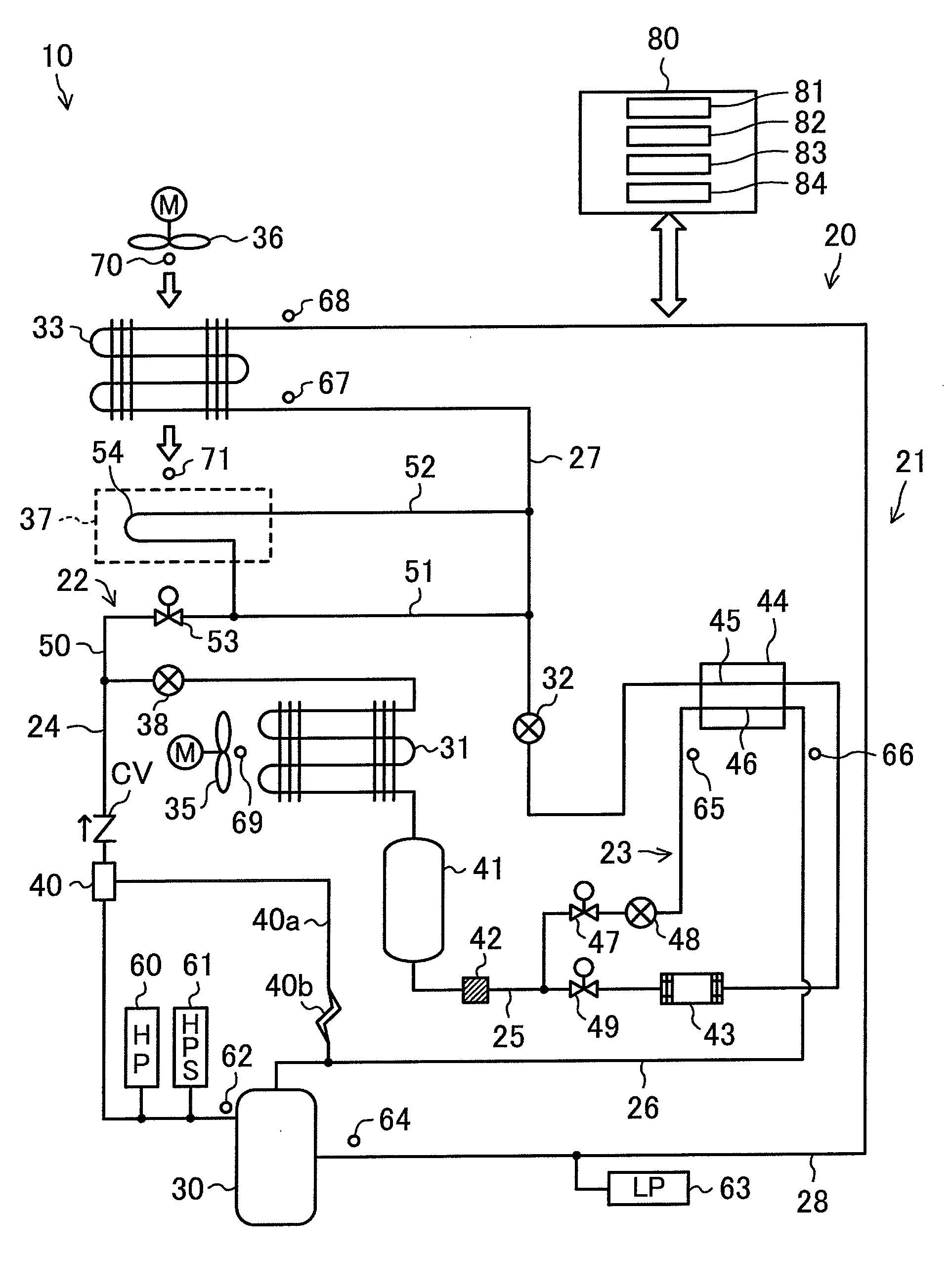
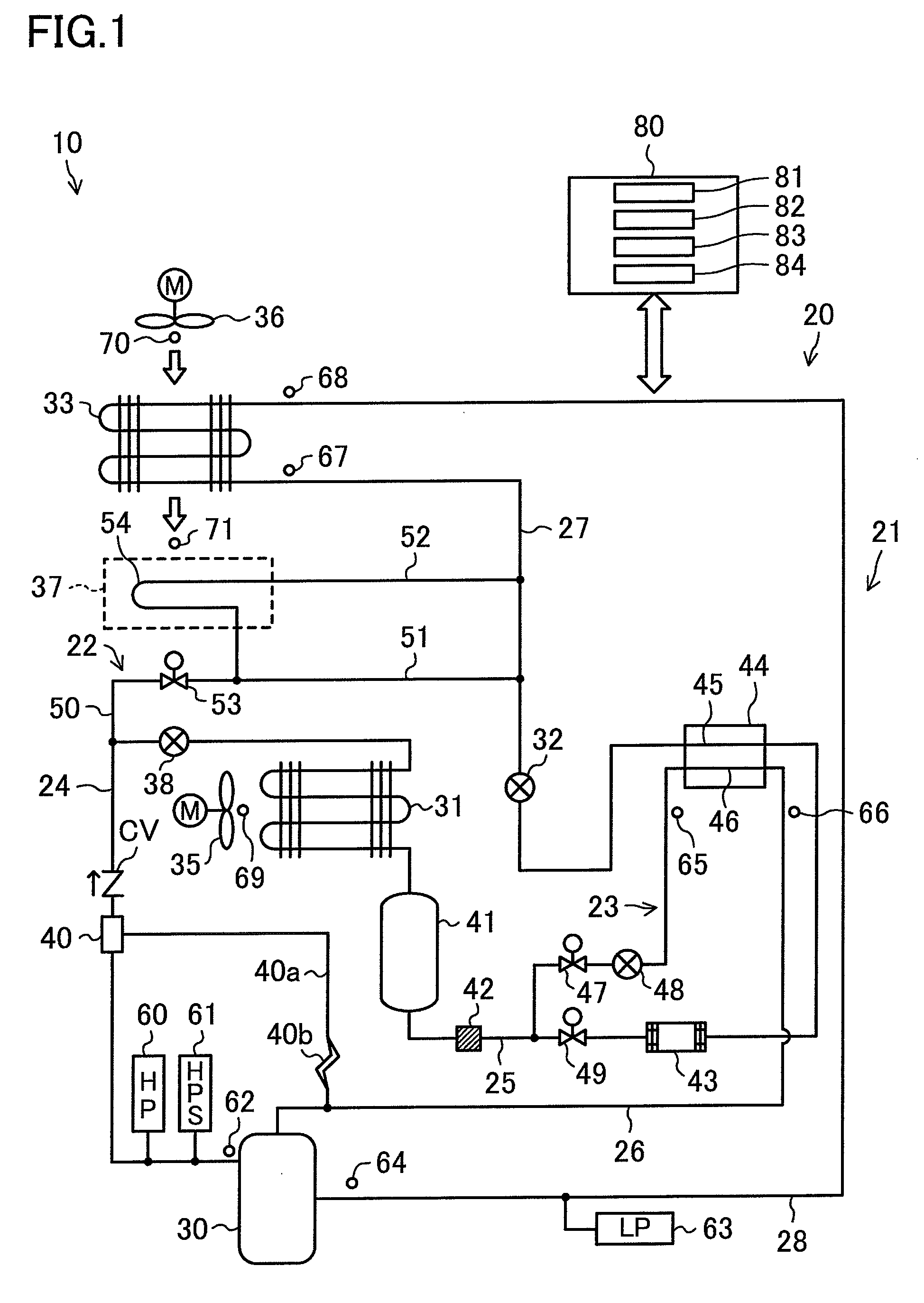
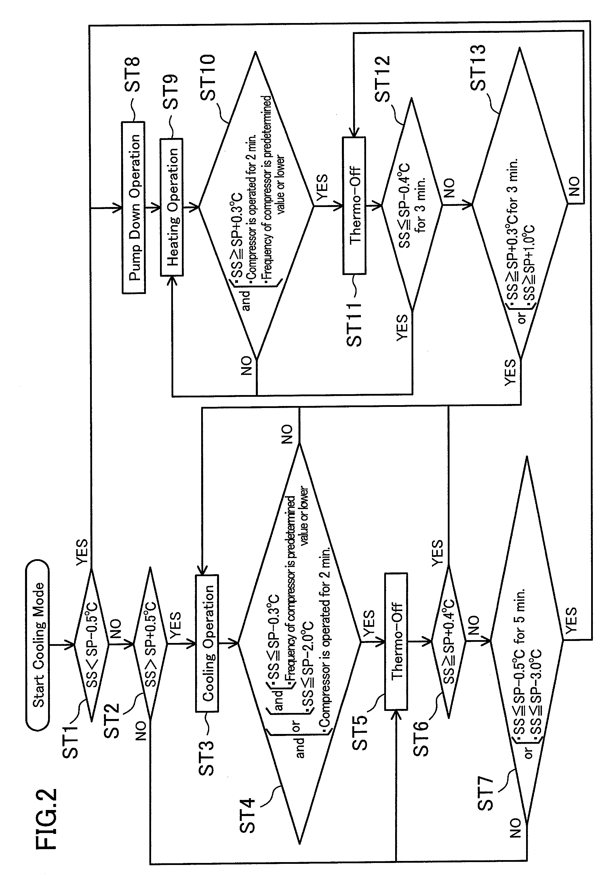
[0019]According to the present invention described above, the operating speed of rotation of the compressor (30) is controlled so that the temperature inside the container reaches the target temperature in the heating operation. This allows appropriate and quick adjustment of the heating capability based on the temperature inside the container. Thus, the temperature inside the container can appropriately and quickly approach the target temperature.
[0020]According to the second aspect of the invention, the amount of the refrigerant circulating between the compressor (30) and the evaporator (33) is adjusted based on the degree of superheat SH of the discharged refrigerant. Specifically, when the degree of superheat SH is low, part of the refrigerant circulating between the compressor (30) and the evaporator (33) is discharged to the high pressure liquid pipe (25), thereby reducing the amount of the circulating refrigerant, and increasing the degree of superheat SH. This can prevent feeding of a two-phase refrigerant to the compressor (30) (i.e., liquid compression in the compressor (30)). When the degree of superheat SH is high, the refrigerant in the high pressure liquid pipe (25) is added to the refrigerant circulating between the compressor (30) and the evaporator (33), thereby increasing the amount of the circulating refrigerant, and reducing the degree of superheat SH. This can prevent abnormal increase in temperature of the refrigerant discharged from the compressor (30), thereby protecting the compressor (30).
[0021]According to the fourth aspect of the invention, the condenser fan (35) is operated in the refrigerant discharge operation. Thus, part of the compressed refrigerant discharged to the condenser (31) can actively be condensed so that the refrigerant is liquefied. As a result, a large amount of the refrigerant can be kept in the condenser (31) or the high pressure liquid pipe (25), thereby performing the refrigerant discharge operation smoothly and reliably.
[0022]According to the fifth aspect of the invention, the evaporator fan (36) is controlled based on the degree of superheat SH of the discharge refrigerant in the heating operation. This can surely prevent feeding of the two-phase refrigerant to the compressor (30) (i.e., liquid compression in the compressor (30)). Thus, the reliability of the container refrigeration apparatus (10) improves.

Problems solved by technology

Specifically, the heating operation is performed when the inside air is excessively cooled, and the temperature of the inside air is too low.

Method used


Image

  • Container refrigeration apparatus
  • Container refrigeration apparatus
  • Container refrigeration apparatus

Examples


embodiment

Advantages of Embodiment

[0077]According to the embodiment described above, in the heating operation in the cooling mode, the operating speed of rotation of the compressor (30) is controlled so that the blown air temperature SS reaches the target temperature SP. Thus, the amount of the circulating refrigerant can quickly be adjusted based on the blown air temperature SS, thereby adjusting the heating capability as appropriate.

[0078]In the above-described embodiment, the amount of the refrigerant circulating between the compressor (30) and the evaporator (33) is adjusted so that the degree of superheat SH of the discharged refrigerant reaches the predetermined value (in the target range). Specifically, when the degree of superheat SH is low, part of the refrigerant circulating between the compressor (30) and the evaporator (33) is released to the high pressure liquid pipe (25) (refrigerant releasing operation), thereby reducing the amount of the circulating refrigerant, and increasing...


PUM


Abstract

A container refrigeration apparatus includes: a refrigerant circuit which performs a refrigeration cycle, and includes a main circuit sequentially connecting a compressor, a condenser, a main expansion valve and an evaporator, and a hot gas bypass circuit through which a refrigerant compressed in the compressor bypasses the condenser and the main expansion valve to flow into the evaporator; and a compressor control section which controls operating speed of rotation of the compressor during heating operation for heating inside of a container by the evaporator while returning the compressed refrigerant from the compressor to the compressor through the hot gas bypass circuit and the evaporator so that a temperature inside the container reaches a target temperature.

Description

TECHNICAL FIELD[0001]The present invention relates to container refrigeration apparatuses, particularly to measures to improve reliability of the container refrigeration apparatuses.BACKGROUND ART[0002]A container refrigeration apparatus for cooling the inside of a container is an example of refrigeration apparatuses for performing a refrigeration cycle. Patent Document 1 discloses a container refrigeration apparatus of this type.[0003]The container refrigeration apparatus disclosed by Patent Document 1 includes a refrigerant circuit connecting a compressor, a condenser, an expansion valve, and an evaporator. The evaporator is provided inside a container. In the evaporator, a refrigerant absorbs heat from the air inside the container to evaporate, thereby cooling the inside air.[0004]A bypass circuit is provided in the refrigerant circuit of the container refrigeration apparatus to supply the refrigerant compressed in the compressor (so-called hot gas) directly to the evaporator wit...

Claims


Application Information

Patent Timeline
IPC IPC(8): F25B49/02F25D17/06
CPCF25B41/04Y02B40/32F25B2400/13F25B2400/19F25B2600/0253F25B2600/2507F25B2700/1931F25B2700/1933F25B2700/2103F25B2700/2106F25B2700/21151F25B2700/21152F25B2700/21172F25B2700/21173F25B2700/21174F25B2700/21175F25D11/003F25D31/005Y02B30/741F25B2400/0403Y02B30/70Y02B40/00F25B41/20F25B41/24
Inventor YOKOHARA, KAZUMAFUJIMOTO, YUUSUKEOKAMOTO, ATSUSHI
Owner DAIKIN IND LTD
Learn More