Fluid flow control device

a flow control device and fluid flow technology, applied in mechanical equipment, transportation and packaging, valve types, etc., can solve the problems of increasing the flow velocity, affecting affecting the operation of the fluid flow control device. , to achieve the effect of increasing the flow rate of fluid, and reducing the cost of manufacturing

Inactive Publication Date: 2012-11-01
SDD CO LTD
View PDF11 Cites 4 Cited by
  • Summary
  • Abstract
  • Description
  • Claims
  • Application Information

AI Technical Summary

Benefits of technology

[0023]According to the present invention, since the fluid flow control device is manufactured in such a way that the fluid pathways are formed along the circumferential surfaces of the cylinders and the cylinders having the fluid pathways are overlapped in order, it can be manufactured more easily and inexpensively than the prior arts.
[0024]Furthermore, a side of a lower end of each upper fluid pathway is overlapped with a side of an upper end of each lower fluid pathway on the same line where ends of the fluid pathways vertically adjacent to each other are parallel to the ground, such that a continuous flow rate is formed when opening of the plug inscribing with the fluid flow control device is changed.
[0025]Moreover, since there are no cross-sectional changes of the upstream side and the downstream side at the fluid resistance area of each fluid pathway, an excessive pressure ratio, which may be a noise source, is not formed. Additionally, since there is no sudden reduction of the cross-section area in the whole zone of the fluid pathway, introduced materials can be discharged to the outside without stopping in the fluid pathway.
[0026]Furthermore, since a local fluid resistance is increased through a repeatedly sudden change of the fluid pathway direction and a multi-stage and multi-path flow, which has a larger cross-sectional area than the prior arts by utilizing the circumferential surface of the cylinders is formed, the present invention can increase the flow rate of the fluid within the uniform volume of the device. Thus, the present invention can easily control the flowing of the fluid even under extra high pressure or high differential pressure conditions, prevent the damage due to noise, vibration, Flow-Accelerated Corrosion, and so on, and make the device small-sized.
[0027]Moreover, the horizontally adjacent fluid pathways out of the fluid pathways formed in the cylinders are inclined in such a way as to face each other, whereby the present invention can prevent the turbulence phenomenon of the fluid, local cavitation, flashing, hammering, and so on.
[0028]Additionally, in case of gas, the present invention regulates the height of the fluid pathways and the thickness of the cylinders in order to increase the volume of the fluid pathways to thereby effectively accept a volume increase due to the spread of the fluid, whereby the present invention can effectively reduce velocity and pressure of gas.

Problems solved by technology

However, if the kinetic energy is more than 1,030 kPa, it may cause severe damages on the fluid flow control device and apparatuses on which the fluid flow control device is mounted.
Furthermore, the fluid flow control device must also give consideration of noise, and in this case, the primary noise source is aerodynamic noise.
Thus, it locally causes an increase of flow velocity of the fluid and a sudden change of pressure, and hence, it may cause noise, vibration, Flow-Accelerated Corrosion, and so on and deteriorate performance of the device due to foreign substances stuck on a portion that the cross-sectional area becomes narrowed.
This may cause the static pressure at that point to reach the vapor pressure of the liquid and consequently force partial vaporization of the jets.
The invention of prior art decreases noise, but since the pressure ratio of the upstream pressure of the slots to the downstream pressure of the slots is excessive, noise is still generated under specific driving conditions.
Furthermore, since the prior art artificially generates cavitation by accelerating the kinetic energy of the fluid, noise and vibration are caused under the specific driving conditions, and thus, it may cause cavitation damage in the device and adjacent structures.
Accordingly, in order to control the kinetic energy and the flow rate of the fluid to a proper level, the size of the device is relatively increased, and hence, an occupation space of the device is also increased and it costs a great deal.
In this case, when the fluid flows from the outside to the inside of the fluid flow control device, vortex occurs inside the fluid flow control device, and it causes non-uniform flowing and pressure distribution.
Thus, it may cause cavitation, flashing or hammering.

Method used


Image

  • Fluid flow control device
  • Fluid flow control device
  • Fluid flow control device

Examples


embodiment 1

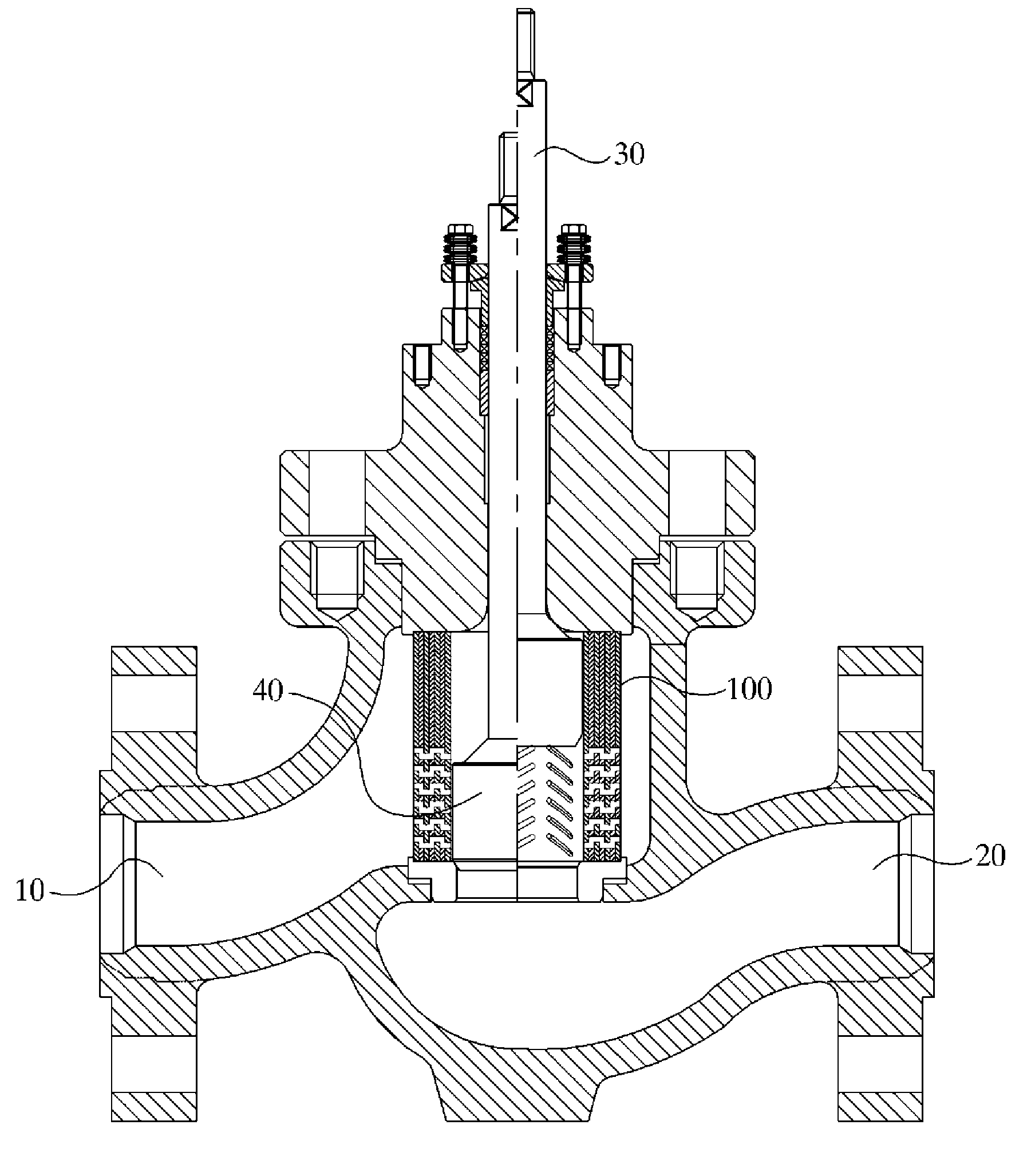
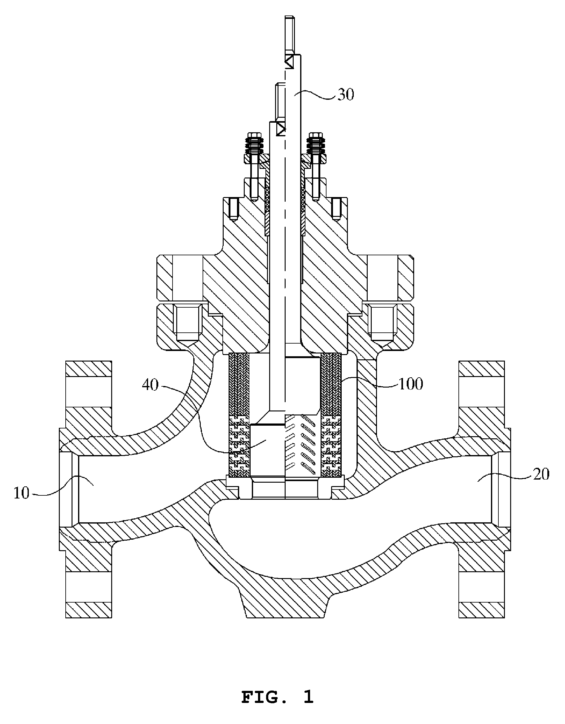
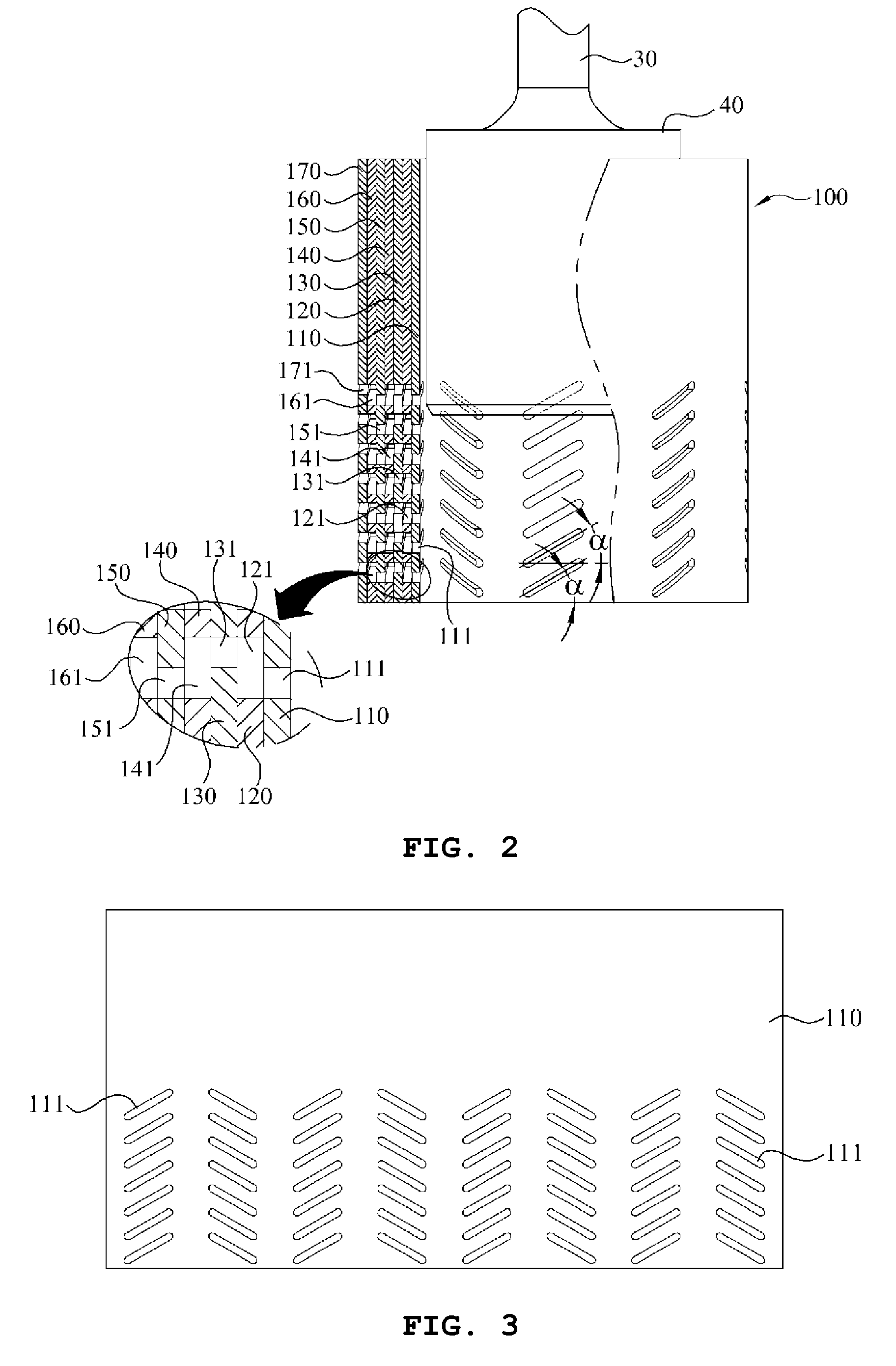
[0067]FIG. 2 is a partially sectional view of a fluid flow control device according to a first embodiment of the present invention, and FIG. 3 is a development view of a cylinder according to the first embodiment. The fluid flow control device 100 according to the first preferred embodiment of the present invention basically includes three cylinders of a first cylinder 110, a second cylinder 120, and a third cylinder 130.

[0068]FIG. 5 is a fluid flow diagram showing fluid moving patterns within the fluid flow control device according to the preferred embodiment, and FIG. 6 is a fluid flow diagram showing fluid moving patterns within the fluid flow control device according to the prior art. The first cylinder 110 according to the first embodiment is in a cylindrical shape having an inner circumference corresponding to an outer circumference of the plug 40 within the fluid flow control device 100 illustrated in FIG. 1. The first cylinder 110 includes a first fluid pathway 111 of an elo...

embodiment 2

[0077]FIG. 9 is a partially sectional view of a fluid flow control device according to a second embodiment of the present invention, and FIG. 10 is a graph showing a flow rate according to opening of a plug of the fluid flow control device according to the second embodiment. As shown in FIG. 9, the fluid flow control device 100 according to the second embodiment of the present invention is generally similar to the first embodiment. As shown in FIG. 10, for a case that a gradual increase of flow rate according to the opening of the plug 40 is needed, the fluid flow control device 100 is constructed in such a way that inclination angles of the first to third fluid pathways 111 to 131 of the first to third cylinders 110 to 130 are decreased from the lower portion toward the upper portion. In other words, in case that seven longitudinal fluid pathways are formed, angles made between the seven fluid pathways and the ground are respectively designated as a1, a2, a3, a4, a5, a6 and a7 star...

embodiment 3

[0078]FIG. 11 is a partially sectional view of a fluid flow control device according to a third embodiment of the present invention. As shown in FIG. 11, the fluid flow control device 100 according to the third embodiment of the present invention is generally similar to the first preferred embodiment. For a case that a gradual increase of flow rate according to the opening of the plug 40 as described in the second embodiment is needed, the longitudinal fluid pathways out of the first to third fluid pathways 111 to 131 of the first to third cylinders 110 to 130 are gradually higher upwardly from the lower portion. As shown in FIG. 11, heights of the seven longitudinal fluid pathways are indicated as W1 to W7, and the flow path is formed in such a way that the heights of the fluid pathways are increased in order of W1, W2, W3, W4, W5, W6 and W7, namely, W234567. Also in the above case, a graph for the flow rate relative to the opening identical to the graph of FIG. 10 can be obtained....


PUM


Abstract

Disclosed therein is a fluid flow control device having a cylinder assembly, which includes cylinders overlapped with each other and fluid pathways for controlling flow rate and velocity of fluid, comprising: a first cylinder having a plurality of first fluid pathways of an elongated form horizontally permeating the cylinder from a central axis; a second cylinder disposed on the outer circumference of the first cylinder; and a third cylinder disposed on an outer circumference of the second cylinder.

Description

TECHNICAL FIELD[0001]The present invention relates to a fluid flow control device, and more particularly, to a fluid flow control device comprising a cylinder assembly, which is capable of preventing side effects, such as noise, vibration and cavitation, which may be caused by fluid, and precisely controlling fluid by converting the fluid into a proper kinetic energy under high differential pressure conditions and in limited usable volumes.BACKGROUND ART[0002]In general, a fluid flow control device is mounted in a fluid regulator, such as valves, in order to properly control kinetic energy of fluid flowing therethrough. Ultimately, the fluid flow control device is to control pressure, velocity, flow rate, noise, cavitation, and so on of the fluid into a proper level. The kinetic energy of the fluid is determined according to the flowing velocity of the fluid. Furthermore, the flowing velocity of the fluid is directly associated with a local loss (local fluid resistance) determined b...

Claims


Application Information

Patent Timeline
Patent Type & Authority Applications(United States)
IPC IPC(8): F16K17/00
CPCF16K47/08Y10T137/7722Y10T137/86759
Inventor KIM, YOUNG BUM
Owner SDD CO LTD
Why Eureka
Try Eureka