
Moveable catenary system for carrying containers using an electric container freight train

a technology of electric container and freight train, which is applied in the direction of trolley lines, vehicle components, power supply lines, etc., can solve the problems of environmental pollution, complex rail track arrangement of container loading and unloading system, and may system installation costs, so as to simplify the arrangement of rails and reduce the period of time , the effect of simplifying the rail track arrangemen

Active Publication Date: 2012-11-01
KIM YEONWON
View PDF14 Cites 4 Cited by
  • Summary
  • Abstract
  • Description
  • Claims
  • Application Information

AI Technical Summary

Benefits of technology

[0035]Accordingly, the present invention has been made in an effort to solve the above-mentioned problems occurring in the prior arts, and it is an object of the present invention to provide a moveable catenary system for carrying containers using an electric container freight train, which can reduce a period of time to move freight cars of the electric container freight train alongside a freight platform and to load the containers onto the freight cars of the freight train or unload the containers from the freight cars and can simplify the rail track arrangement.
[0044]According to the present invention, in the state where the electric container freight train moves along the main rail track and stops beside the freight platform, because the electric container freight train travels along the main rail track directly after the containers are loaded onto or unloaded from the freight cars of the electric container freight train, the moveable catenary system of the present invention can reduce the period of time to load or unload the containers onto or from the freight cars and simplify the rail track arrangement.
[0045]Therefore, the arrangement of rails of the track is simplified and the area of the land to install the rails is reduced. Accordingly, the present invention can reduce system installation costs.
[0046]Furthermore, the moveable catenary system according to the present invention does not need the diesel locomotive for moving the freight cars, and hence, can prevent air pollution and noise.

Problems solved by technology

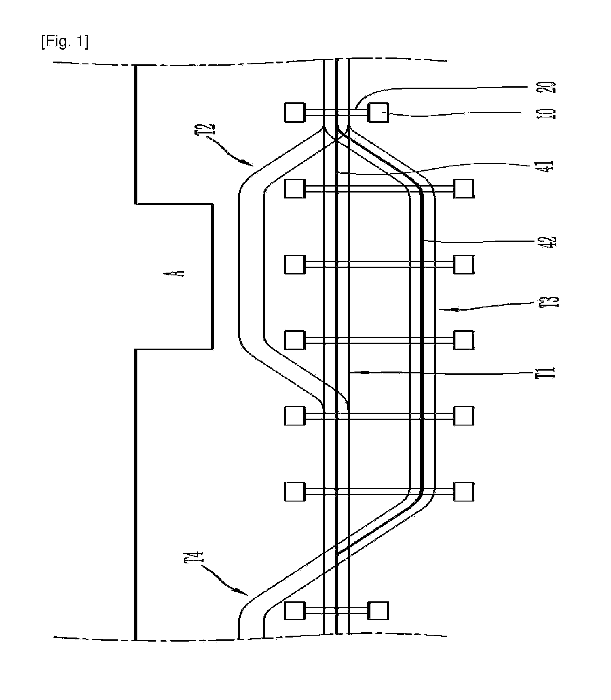
Moreover, the container loading and unloading system according to the prior art has another problem in that the container loading and unloading system is complex in rail track arrangement and requires may system installation costs because it requires a wide site because it needs the train standby rail track T4 where the diesel locomotive stands by, the auxiliary rail track T3 where the electric locomotive stands by, and the freight loading rail track T2 for loading and unloading the containers.
Furthermore, the container loading and unloading system according to the prior art has a further problem in that it causes environmental pollution and generates noise because the diesel locomotive generates exhaust gas.
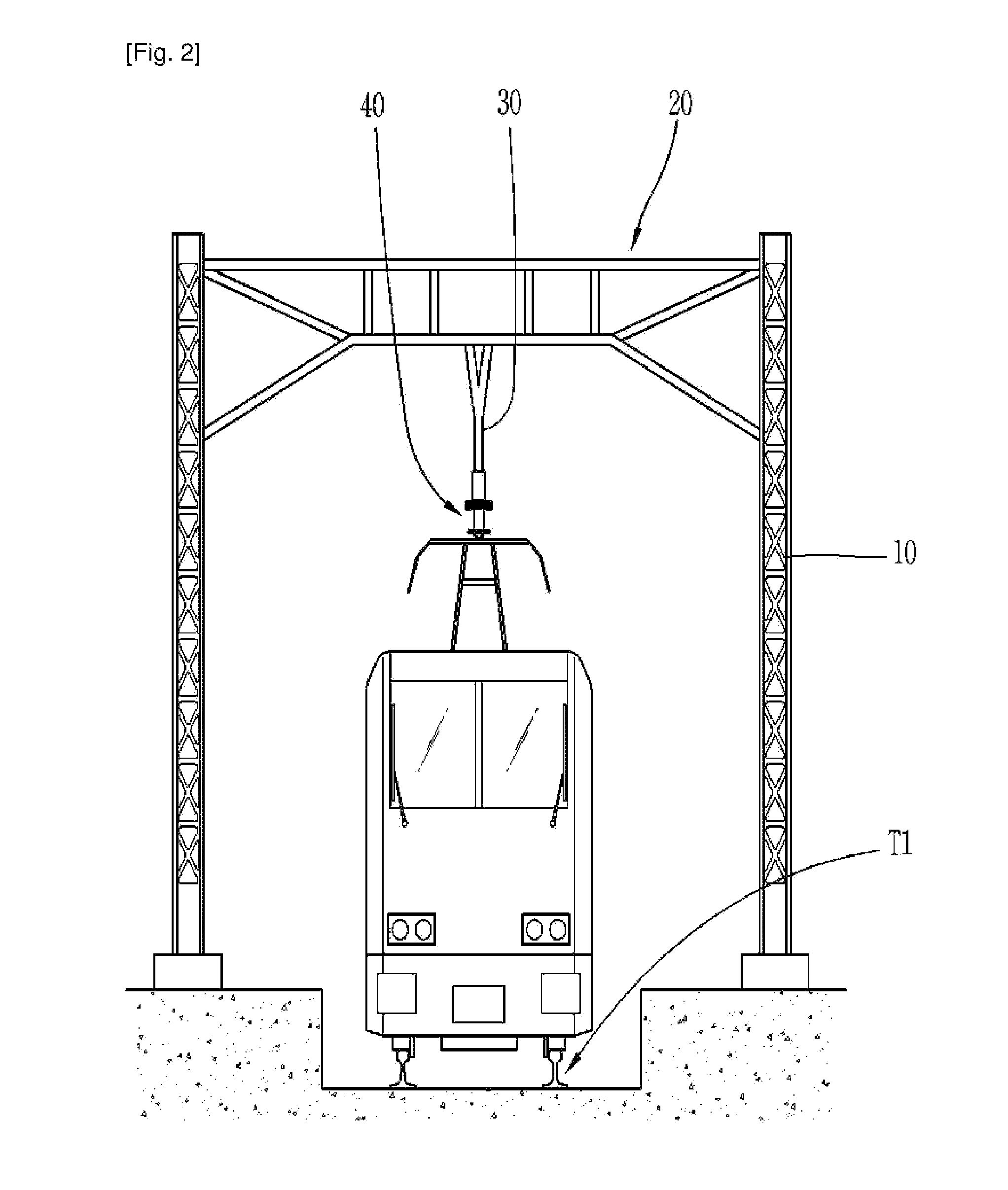
Additionally, because the trolley line for supplying electric energy to the electric locomotive is located on above the containers, the rail transfer crane or the reach stacker cannot lift up the containers from the freight cars in the state where the freight cars are connected to the electric locomotive.

Method used


Image

  • Moveable catenary system for carrying containers using an electric container freight train
  • Moveable catenary system for carrying containers using an electric container freight train
  • Moveable catenary system for carrying containers using an electric container freight train

Examples


Embodiment Construction

[0059]Reference will be now made in detail to the preferred embodiment of the present invention with reference to the attached drawings.

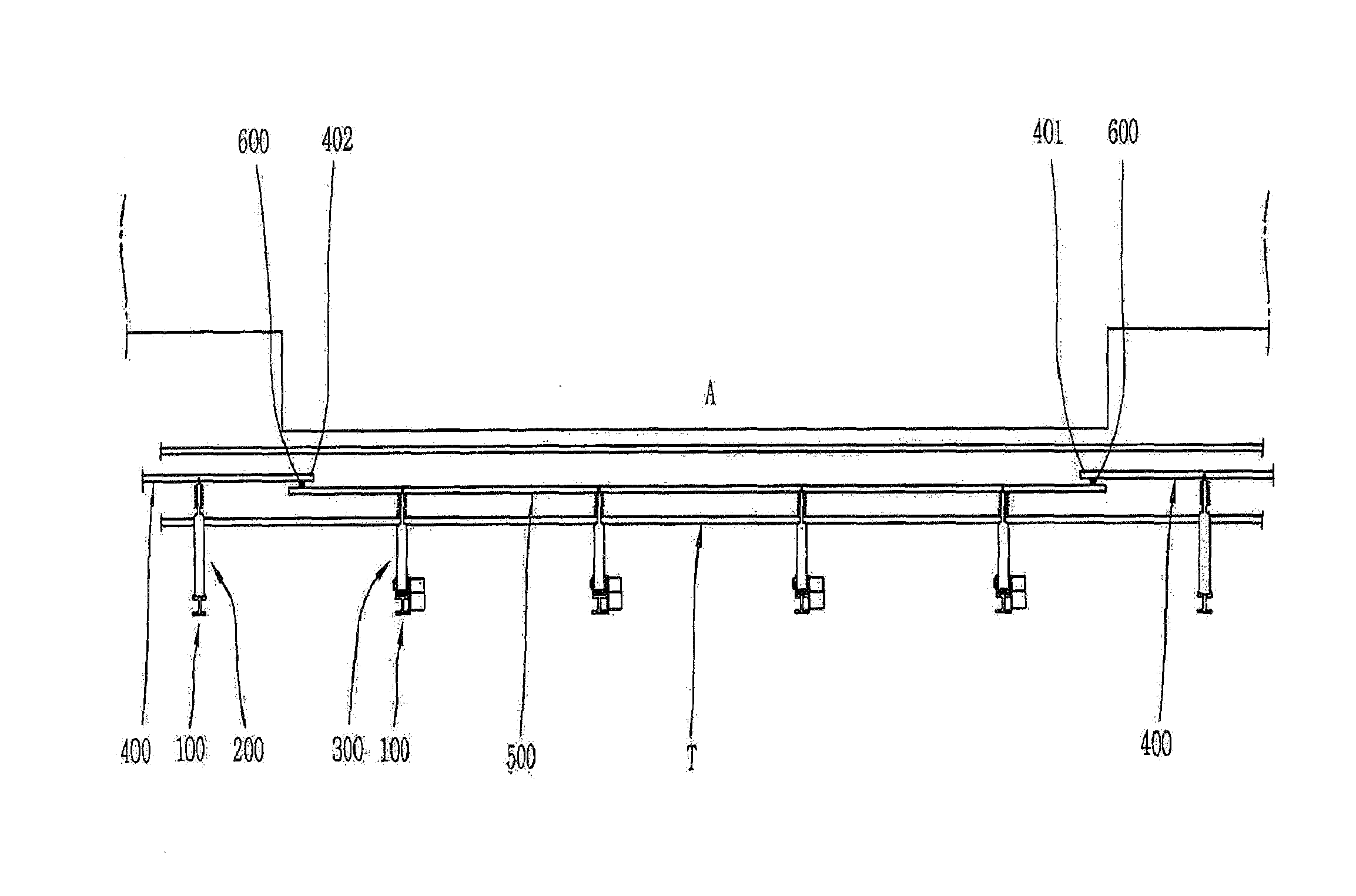
[0060]FIG. 3 is a plan view of a moveable catenary system for carrying containers using an electric container freight train according to a first preferred embodiment of the present invention, and FIG. 4 is a rear view of the electric container freight train located on the moveable catenary system for carrying containers according to the first preferred embodiment of the present invention.

[0061]As shown in FIGS. 3 and 4, the moveable catenary system for carrying containers using the electric container freight train according to the first preferred embodiment of the present invention includes a main rail track T, catenary masts 100, fixed support units 200, vertical driving support units 300, a fixed catenary 400, a moveable catenary 500, and a switching unit 600.

[0062]A freight platform A is located near by the main rail track T. The main rail track ...


PUM


Abstract

A moveable catenary system for carrying a container using an electric container freight train includes: a main rail track disposed beside a freight platform; a plurality of catenary masts disposed beside the main rail track; fixed support units fixedly coupled in a cantilever shape to the catenary masts, respectively, with the exception of the catenary masts corresponding to the freight platform; vertical driving support units coupled in the cantilever shape to the catenary masts corresponding to the freight platform so as to vertically rotate the catenary masts, respectively; a fixed catenary coupled to the fixed support units such that positions at which the vertical driving support units are disposed are cut and the vertical driving support units are disposed inside and along the main rail track; a moveable catenary connected to the vertical driving support unit, the movable catenary being circularly moved in a vertical direction according to the vertical rotation of the vertical driving support units; and switching units connecting the moveable catenary to the fixed catenary when the vertical driving support units are disposed in a horizontal direction. According to the present invention, freight cars of the electric container freight train may be moved beside the freight platform to reduce the time required for loading containers into the freight cars of the electric container freight train or unloading containers mounted on the freight cars. Furthermore, the rail track may be simply arranged.

Description

BACKGROUND OF THE INVENTION[0001]The present invention relates to a moveable catenary system for carrying containers using an electric container freight train.[0002]Containers are used for carrying freight. The containers are easy to pack up and carry luggage and can protect freight put in the containers. The containers are divided into overland containers and marine containers.[0003]The overland containers are mainly carried using trailers or freight trains.[0004]In the case that the containers are carried using the freight train, the containers are carried while the freight train travels back and forth between two or more railroad container distribution stations, where rail tracks are located. The containers loaded at a container yard of the railroad container distribution station are carried to a destination using overland transportation means or marine transportation means.[0005]FIG. 1 is a schematic plan view showing a part of a container carrying system using an electric conta...

Claims


Application Information

Patent Timeline
Patent Type & Authority Applications(United States)
IPC IPC(8): B60M1/18B60M1/13
CPCB60M1/18B60M1/12B60M1/13
Inventor KIM, YEONWON
Owner KIM YEONWON
Learn More