Stator for rotating electrical machine

a technology of rotating electrical machines and stators, which is applied in the direction of windings, dynamo-electric components, and prefabricated windings. it can solve the problems of difficult to increase the space factor of coils, the shape of slots or teeth may not be optimized, and the width of unnecessary teeth can be reduced, and the proportion of the cross-sectional area of coils to that of the stator can be easily increased. , the effect of maximizing the space inside the slots

Inactive Publication Date: 2012-11-01
AISIN AW CO LTD
View PDF10 Cites 31 Cited by
  • Summary
  • Abstract
  • Description
  • Claims
  • Application Information

AI Technical Summary

Benefits of technology

[0005]To solve this problem, a stator for a rotating electrical machine, capable of simplifying a process of winding wire around a stator core and capable of increasing the space factor of coils regardless of the shape of slots, is desired.

Problems solved by technology

In such a stator for a rotating electrical machine including coils structured using conductor wires with circular cross-sections, gaps are easily left between the conductor wires in slots, and therefore it is difficult to increase a space factor of the coils.
Although a reduction of the diameter of the conductor wires may be effective in reducing the size of the gaps between the conductor wires to increase the space factor, a reduction of the diameter of the conductor wires may require, for example, devices to prevent breaks in the conductor wires during winding of the conductor wires around the stator core, and a long time in a winding process due to the increased number of turns around the stator core.
However, the shapes of the slots are substantially limited to rectangles, and the shapes of the slots or teeth may not be optimized.

Method used


Image

  • Stator for rotating electrical machine
  • Stator for rotating electrical machine
  • Stator for rotating electrical machine

Examples


Embodiment Construction

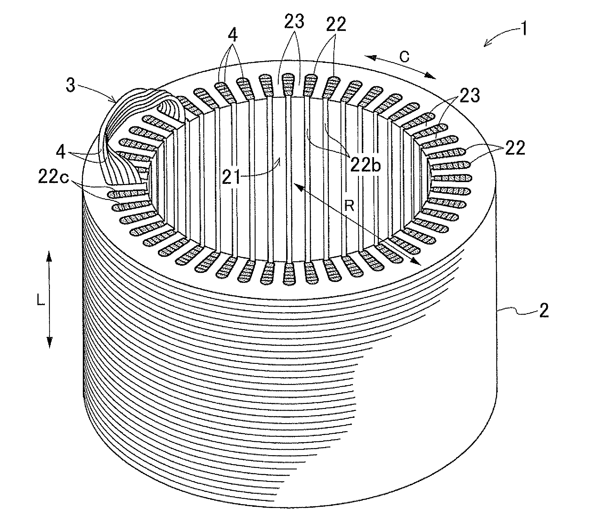
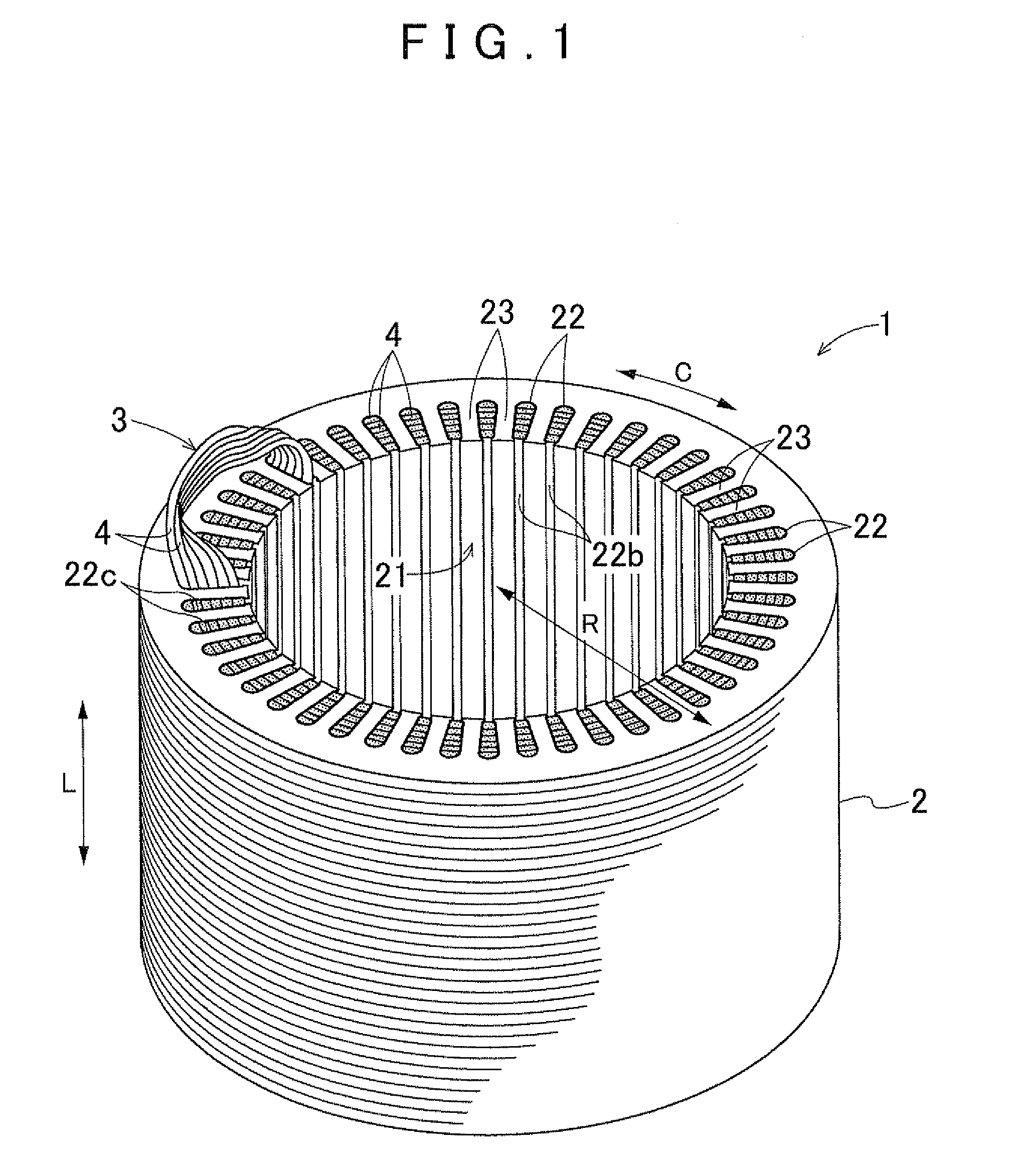
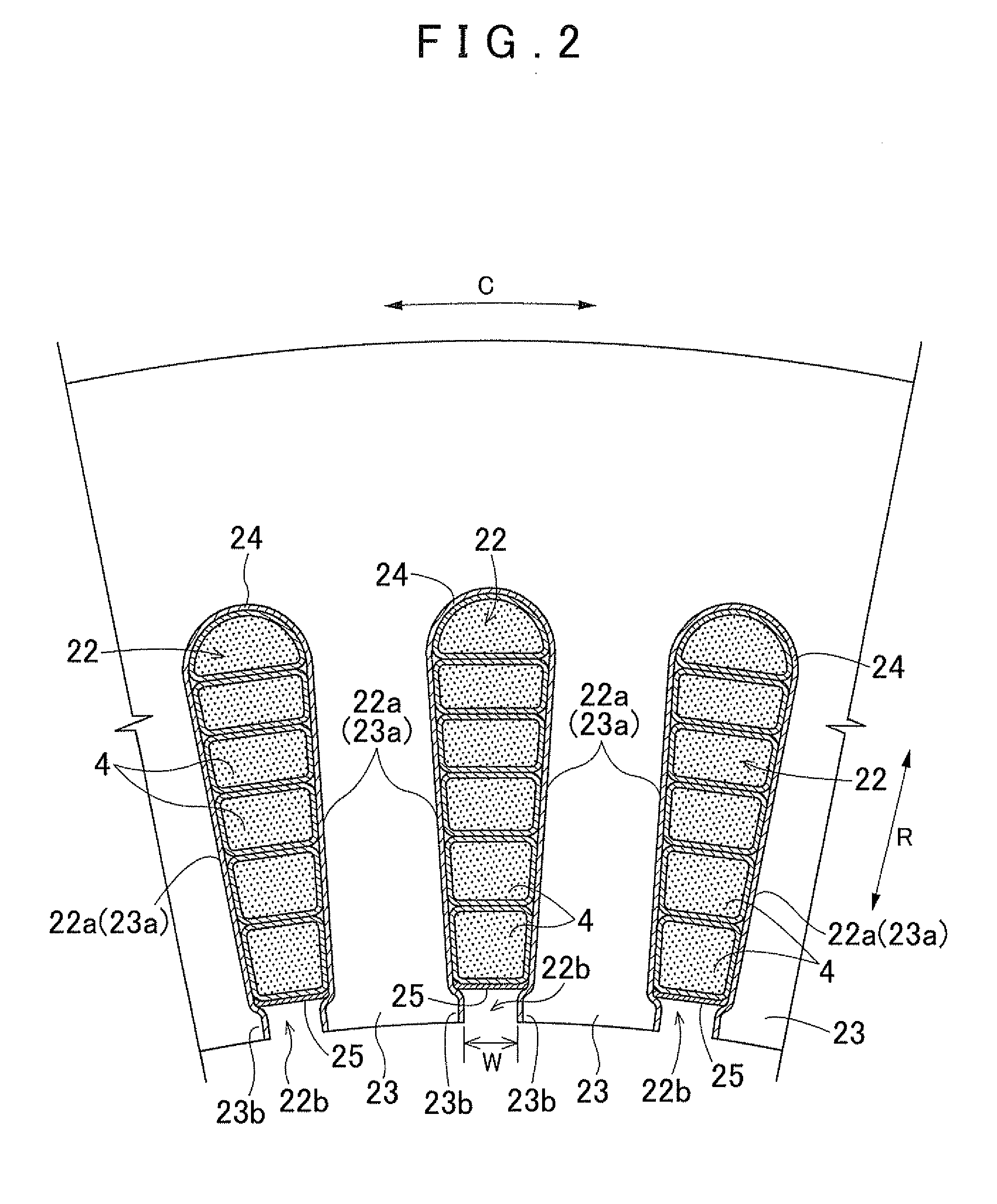
[0033]A stator for a rotating electrical machine according to an embodiment of the present invention will now be described with reference to the drawings. Herein, an example of the stator for the rotating electrical machine according to the present invention applied to a stator 1 of a rotating electrical machine of the inner rotor type will be described. The stator 1 according to this embodiment includes a stator core 2 and coils 3 attached to the stator core 2 as illustrated in FIG. 1. The coils 3 are structured by winding covered conductor wire bundles 4 around the stator core 2. As illustrated in FIG. 3, the covered conductor wire bundles 4 each have a structure in which an outer circumference 42a of a conductor wire bundle 42 consisting of an assembly of a plurality of conductor wires 41 is covered with a flexible insulating cover 43. The stator 1 according to this embodiment is characterized in that the stator 1 uses such covered conductor wire bundles 4. The structure of the s...


PUM


Abstract

A stator for a rotating electrical machine includes a stator core with a plurality of slots; and coils attached to the stator core. The coils are each structured by winding a covered conductor wire bundle around the stator core. The covered conductor wire bundle is structured by covering an outer circumference of a conductor wire bundle with a flexible insulating cover, the conductor wire bundle consisting of an assembly of a plurality of conductor wires. A plurality of the covered conductor wire bundles is disposed in each slot such that adjacent pairs of the covered conductor wire bundles are in contact with each other.

Description

INCORPORATION BY REFERENCE[0001]The disclosure of Japanese Patent Application No. 2011-101477 filed on Apr. 28, 2011 including the specification, drawings and abstract is incorporated herein by reference in its entirety.BACKGROUND OF THE INVENTION[0002]The present invention relates to a stator for a rotating electrical machine including a stator core with a plurality of slots and coils attached to the stator core.DESCRIPTION OF THE RELATED ART [0003]Up to now, a rotating electrical machine serving as an electric motor or a power generator has used a stator for a rotating electrical machine including a stator core with a plurality of slots and coils attached to the stator core. For example, Japanese Patent Application Publication No. 09-009588 (JP 09-009588 A) describes a stator for a rotating electrical machine including a stator core with a plurality of slots distributed in the circumferential direction of the stator core and coils structured by winding conductor wires with circula...

Claims


Application Information

Patent Timeline
Patent Type & Authority Applications(United States)
IPC IPC(8): H02K3/12
CPCH02K15/066H02K3/12H02K3/34H02K3/04H02K3/48H02K15/06
Inventor KOGA, KIYOTAKA
Owner AISIN AW CO LTD
Why Eureka
Try Eureka