
High performance time domain reflectometry

a time domain and reflectometry technology, applied in the field of time domain reflectometry, can solve the problems of data communication errors, limited tdr probes, and limited tdr launch construction, so as to facilitate the alignment of said spring-loaded pins, provide mechanical stability, and high bandwidth

Inactive Publication Date: 2012-11-01
IBM CORP
View PDF10 Cites 54 Cited by
  • Summary
  • Abstract
  • Description
  • Claims
  • Application Information

AI Technical Summary

Benefits of technology

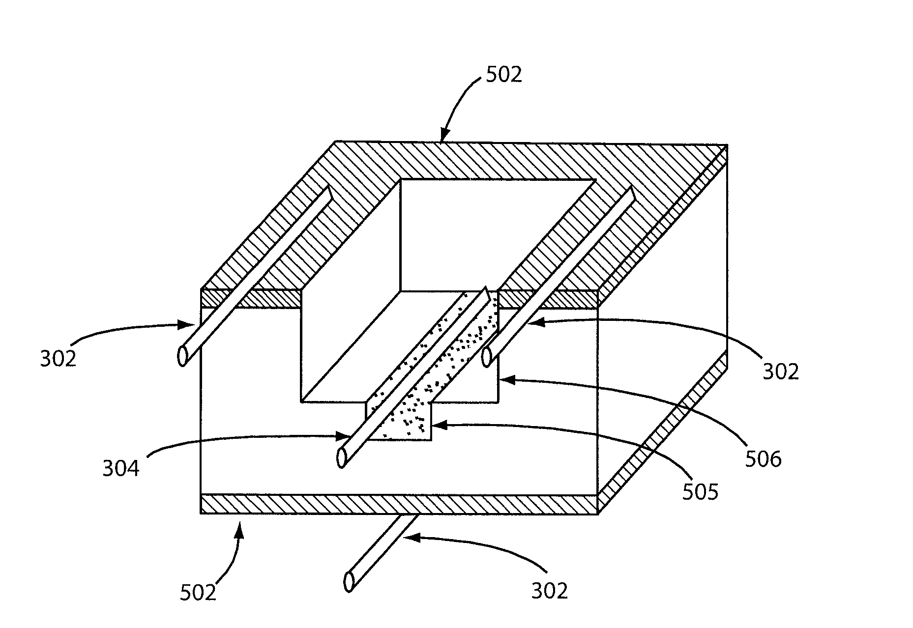
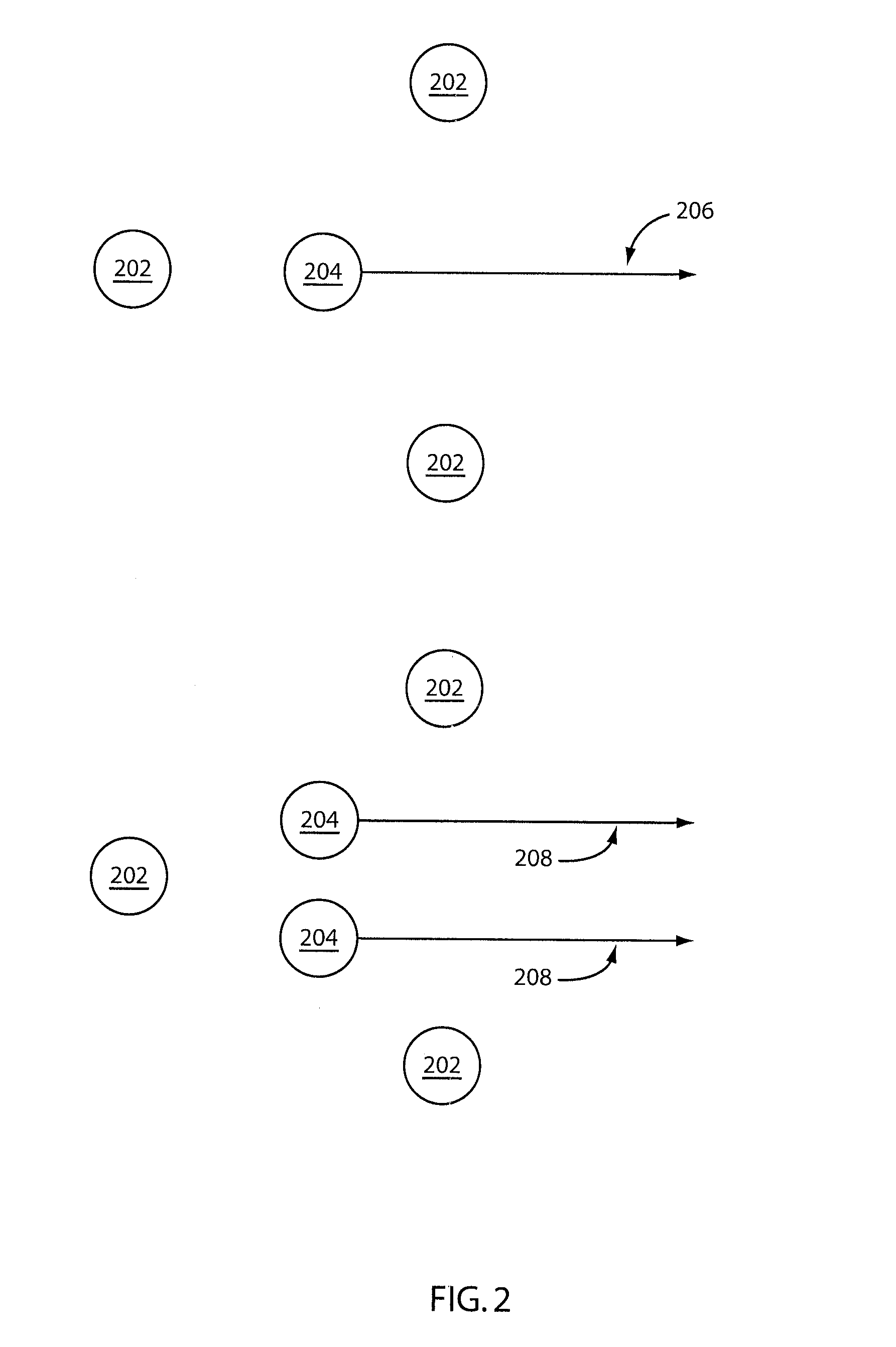
[0008]A time domain reflectometry system is shown that includes a PCB and a probe. The PCB includes at least one signal terminal connected to at least one signal via and at least three guide terminals arranged around the at least one high-frequency signal terminal, wherein at least one of said guide terminals is connected to at least one ground via. The probe includes at least one biased pin to contact the at least one signal terminal and at least three fixed guide pins arranged about the at least one biased pin to facilitate alignment of said at least one biased pin by first engaging at least one guide terminal area, such that the at least one mechanically biased pin is guided to the at least one contact point.
[0009]A high bandwidth time domain reflectometry system is shown that include a PCB and a probe. The PCB includes at least one high-frequency signal terminal; and at least three ground terminals arranged around the at least one high-frequency signal terminal. The probe includes at least one spring-loaded pin to contact signal vias and at least three grounding fixed pins having conical tips formed arranged about the at least one spring-loaded pin to facilitate alignment of said spring-loaded pins and to provide mechanical stability.

Problems solved by technology

If this impedance differs from the impedance of other elements connected by these transmission lines, reflections will occur which can lead to errors in data communication.
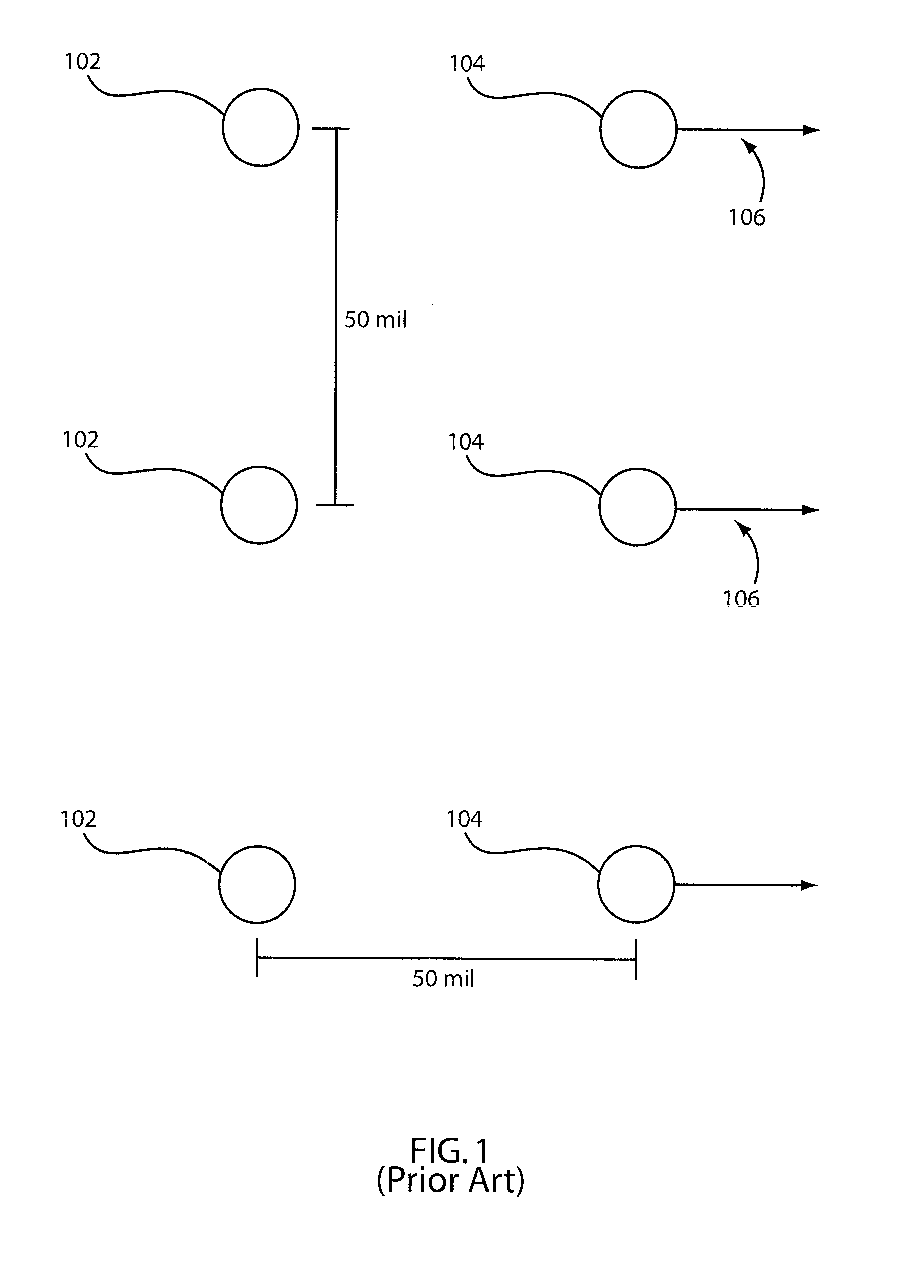
As communications speeds on PCBs has increased, impedance information is now needed at much higher frequencies, and while fast TDR step generator units are readily available, launching a very fast edge onto PCB traces is limited by existing TDR probes and TDR launch construction.

Method used


Image

  • High performance time domain reflectometry
  • High performance time domain reflectometry
  • High performance time domain reflectometry

Examples


Embodiment Construction

[0022]When a signal propagates through a transmission line, changes in impedance can interfere with propagation by attenuating the signal and introducing reflections. As such, the measurement of impedance is an important step in testing. Time domain reflectometry (TDR) helps accomplish this. TDR sends a pulse through the transmission line and measures reflected waveforms that result from impedance changes. Because the speed of propagation is generally stable through a transmission line, measuring the time between pulse and reflection provides information regarding the location of the impedance change. However, the usefulness of TDR can be limited at high frequencies due to limitations in the tools used.

[0023]The size of an impedance discontinuity can be determined from the amplitude of a reflected signal in TDR. Furthermore, the distance of the reflecting impedance from the signal launch can be determined from the time that a pulse takes to return if the transmission properties of t...


PUM


Abstract

Methods and systems for high-bandwidth time domain reflectometry include a printed circuit board (PCB) and a probe. The PCB includes at least one signal terminal connected to at least one signal via at least three guide terminals arranged around the at least one high-frequency signal terminal. At least one of the guide terminals is connected to at least one ground via. The probe includes at least one biased pin to contact the at least one signal terminal and at least three fixed guide pins arranged about the at least one biased pin to facilitate alignment of said at least one biased pin by first engaging at least one guide terminal area, such that the at least one mechanically biased pin is guided to the at least one contact point.

Description

GOVERNMENT RIGHTS[0001]This invention was made with Government support under Contract No.: HR0011-07-9-0002 awarded by Defense Advanced Research Projects Agency. The Government has certain rights to this invention.BACKGROUND[0002]1. Technical Field[0003]The present invention relates to time domain reflectometry and, in particular, to systems for high performance time domain reflectometry using a tripod stabilized probe configuration.[0004]2. Description of the Related Art[0005]Line impedance is a key parameter of fabricated high speed transmission lines in printed circuit boards (PCBs). Time Domain Reflectometry (TDR) is often used to measure impedance using relatively simple test equipment. If this impedance differs from the impedance of other elements connected by these transmission lines, reflections will occur which can lead to errors in data communication. As communications speeds on PCBs has increased, impedance information is now needed at much higher frequencies, and while f...

Claims


Application Information

Patent Timeline
IPC IPC(8): G01R27/28G01R1/06
CPCG01R27/06G01R31/14G01R31/11G01R1/06772
Inventor BAKS, CHRISTIAN W.JOHN, RICHARD A.KWARK, YOUNG H.
Owner IBM CORP
Learn More