Display sheet, method of manufacturing display sheet, display device and electronic apparatus

Inactive Publication Date: 2012-11-01
SEIKO EPSON CORP
View PDF5 Cites 17 Cited by
  • Summary
  • Abstract
  • Description
  • Claims
  • Application Information

AI Technical Summary

Benefits of technology

[0062]In this manner, it is possible to obtain an

Problems solved by technology

However, in the “partition wall type” display device, the aperture ratio (ratio occupied by the effective display region) of the display surface is reduced by the partition walls and there is a problem in that the display characteristics are deteriorated.
In addition to this, the dispersion liquid must be filled inside each cell, and the processing is problematic.
In particular, when it is necessary

Method used


Image

  • Display sheet, method of manufacturing display sheet, display device and electronic apparatus
  • Display sheet, method of manufacturing display sheet, display device and electronic apparatus
  • Display sheet, method of manufacturing display sheet, display device and electronic apparatus

Examples


Example

First Embodiment

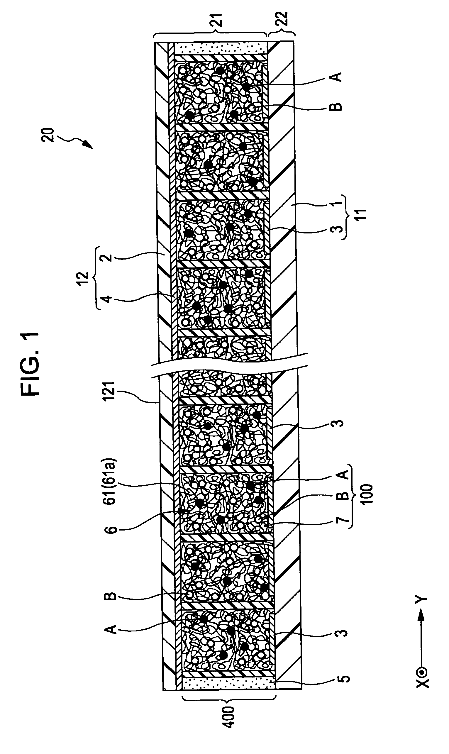
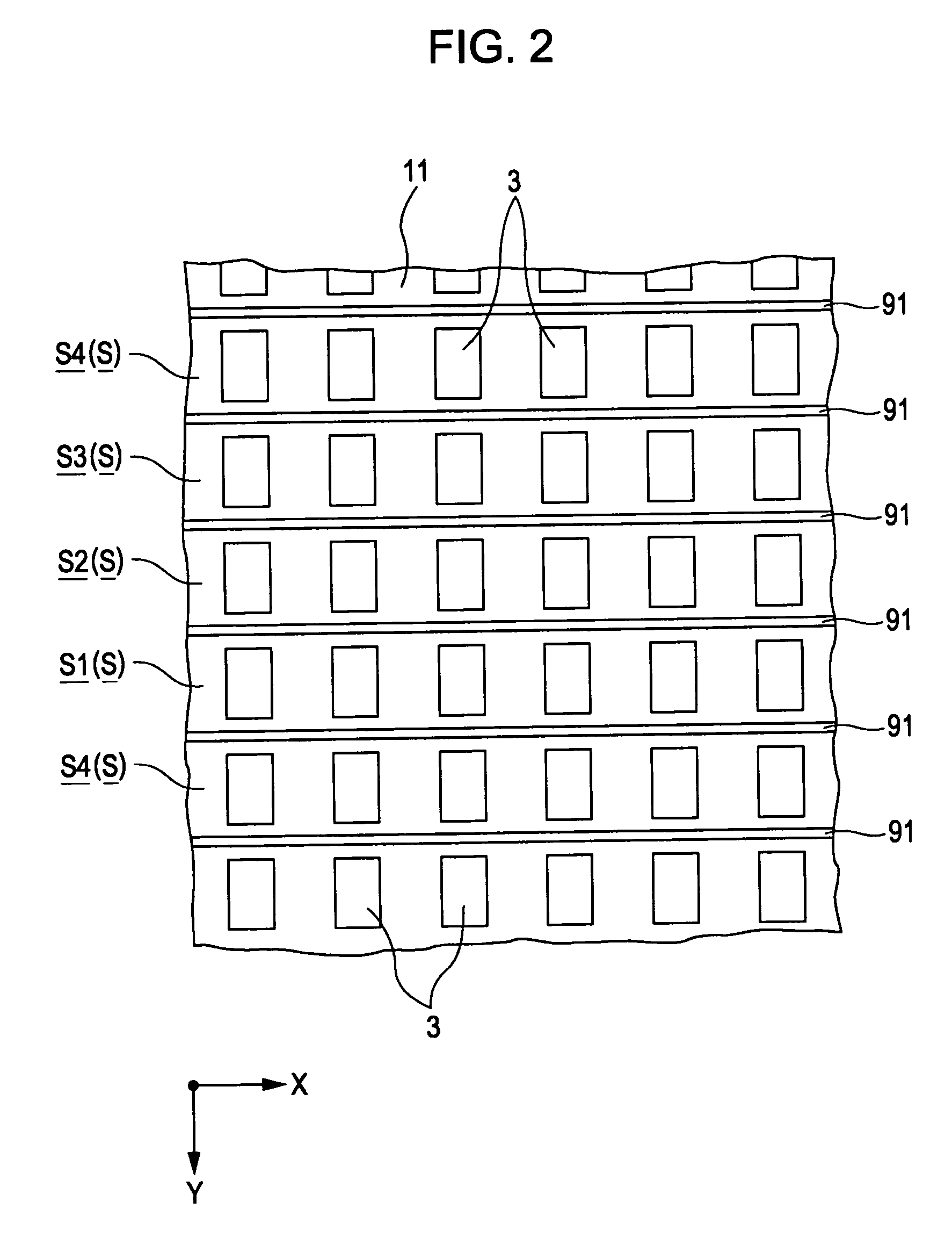
[0080]FIG. 1 is a cross-sectional view showing the display device according to a first embodiment of the present invention, FIG. 2 is a plan view (upper surface view) of the display device shown in FIG. 1, FIG. 3 is a cross-sectional view describing the driving of the display device shown in FIG. 1, and FIG. 4 is a cross-sectional view describing the method of manufacturing the display device shown in FIG. 1. Here, in the following, for ease of description, a description will be given with the upper side in FIG. 1 and FIG. 4 as “up” and the lower side as “down”. In addition, as shown in FIG. 1, the two mutually intersecting directions in the plan view of the display device are set as the “X direction” and the “Y direction”. The same is true for the other figures. In addition, in FIG. 2, for convenience of description, illustration of the substrate 12 and the porous layer 6 is omitted.

[0081]The display device (display device of the present invention) 20 shown in FIG. ...

Example

Second Embodiment

[0150]Next, a description will be given of the display device according to a second embodiment of the present invention.

[0151]FIG. 5 is a cross-sectional view showing the display device according to a second embodiment of the present invention, FIG. 6 is a plan view (upper surface view) of the display device shown in FIG. 5, FIG. 7 is a cross-sectional view describing the driving of the display device shown in FIG. 5, and FIG. 8 is a cross-sectional view describing the method of manufacturing the display device shown in FIG. 5. In addition, in FIG. 6, for convenience of description, illustration of the substrate 12 and the porous layer 6 is omitted.

[0152]Below, a description will be given of the second embodiment focusing on the differences to the above-described embodiment and omitting any description of the similarities.

[0153]The display device according to a second embodiment of the present invention is the same as the display device of the first embodiment other...

Example

Third Embodiment

[0202]Next, a description will be given of the display device according to a third embodiment of the present invention.

[0203]FIG. 9 is a plan view (upper surface view) showing a display device according to a third embodiment of the present invention. In addition, in FIG. 9, for convenience of description, illustration of the substrate 12 and the porous layer 6 is omitted.

[0204]Below, a description will be given of the third embodiment focusing on the differences to the above-described embodiments and omitting any description of the similarities.

[0205]The display device according to a third embodiment of the present invention is the same as the display device of the second embodiment other than the different configuration (shape) of the first partition units. Here, where the configuration is the same as the second embodiment described above, the same reference numerals are used.

[0206]As shown in FIG. 9, each first partition unit 91A extends in the X direction while re...


PUM


Abstract

A display sheet includes a substrate provided at a display surface side; a facing substrate arranged to face the first substrate; a display layer provided between the substrate and the facing substrate; a plurality of first partition units provided in the display layer and dividing the display layer into a plurality of regions in the X direction and extending in the Y direction intersecting the X direction; a porous layer provided inside each of the regions; and a dispersion liquid filled inside each of the regions in which first and second particles are dispersed with a dispersion medium.

Description

TECHNICAL FIELD[0001]The present invention relates to a display sheet, a method of manufacturing a display sheet, a display device and an electronic apparatus.BACKGROUND ART[0002]For example, as the configuration of an image display unit of electronic paper, an electrophoretic display using the electrophoresis of particles is known (for example, refer to Patent Document 1). Electrophoretic displays have superior portability and energy efficiency and are particularly suitable as image display units of electronic paper.[0003]An electrophoretic display has a pair of electrodes arranged to face each other and a display layer provided therebetween, and, in the display layer, for example, there is filled a dispersion liquid in which positively charged white particles and negatively charged black particles are dispersed in a liquid phase dispersion medium. Such an electrophoretic display is configured such that a desired image is displayed by applying a voltage between the pair of electrod...

Claims


Application Information

Patent Timeline
IPC IPC(8): G02B26/02H01J9/20G02F1/167G02F1/1679
CPCG02F1/167G02B26/026G02F2001/1672G09G3/3446G09G3/2003G02F1/1681G02F1/1679
Inventor HAYASHI, KENJI
Owner SEIKO EPSON CORP
Why Eureka
Try Eureka