Device package structure, device packaging method, liquid drop ejection method, connector, and semiconductor device

Inactive Publication Date: 2006-10-19
SEIKO EPSON CORP
View PDF3 Cites 7 Cited by
  • Summary
  • Abstract
  • Description
  • Claims
  • Application Information

AI Technical Summary

Benefits of technology

[0009] An advantage of some aspects of the invention is to provide a device package structure for electrical connection of the connection terminals of an IC chip or other device with the connection portions of a substrate onto which the device is packaged, via level difference portions due to the device and level difference portions arising from the shape of the substrate. The advantage of some aspects of the invention is to pr

Problems solved by technology

However, the above-described technology of the prior art has the following problems.
Co

Method used


Image

  • Device package structure, device packaging method, liquid drop ejection method, connector, and semiconductor device
  • Device package structure, device packaging method, liquid drop ejection method, connector, and semiconductor device
  • Device package structure, device packaging method, liquid drop ejection method, connector, and semiconductor device

Examples


Example

First Embodiment

[0157] Liquid Drop Ejection Head

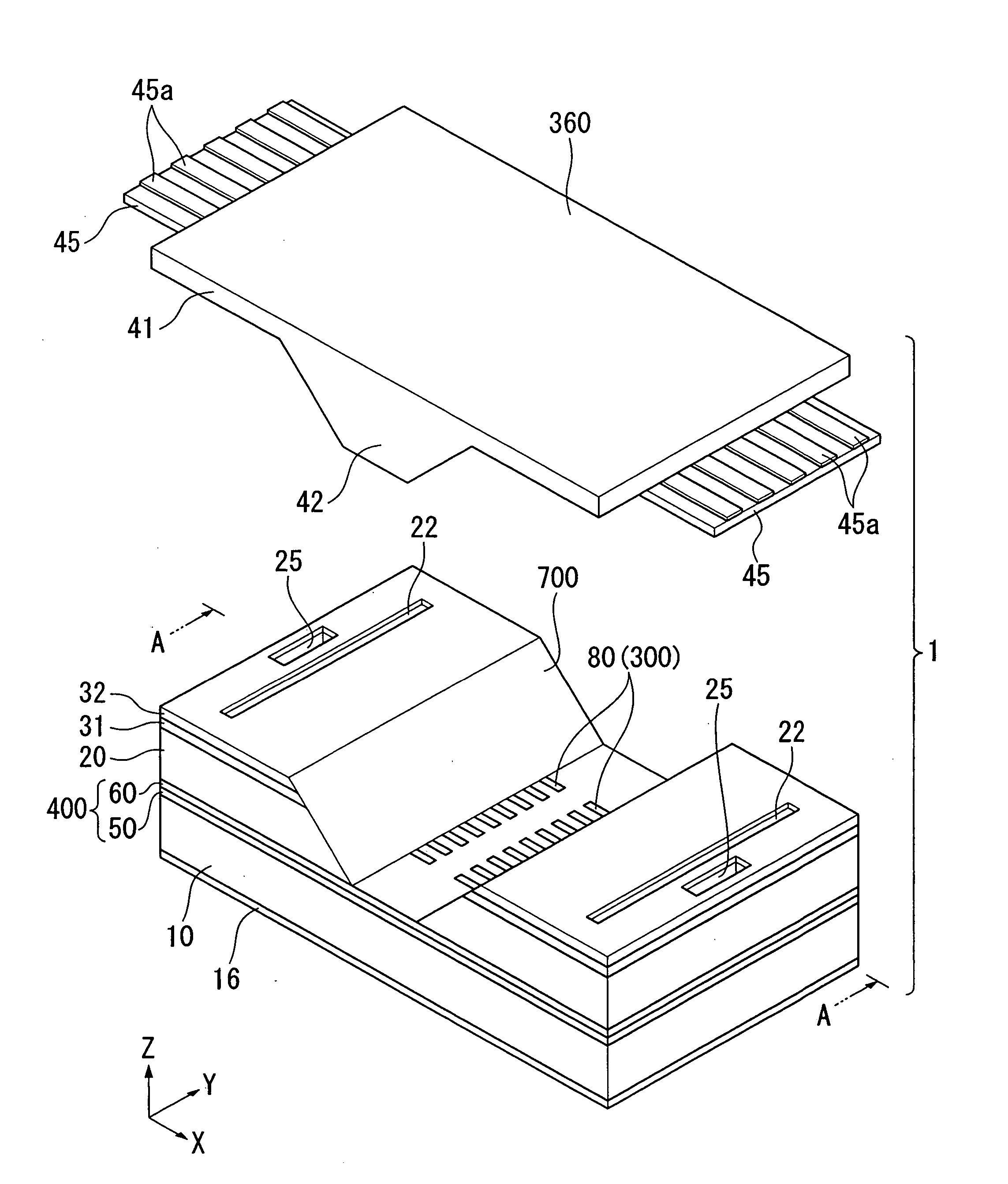
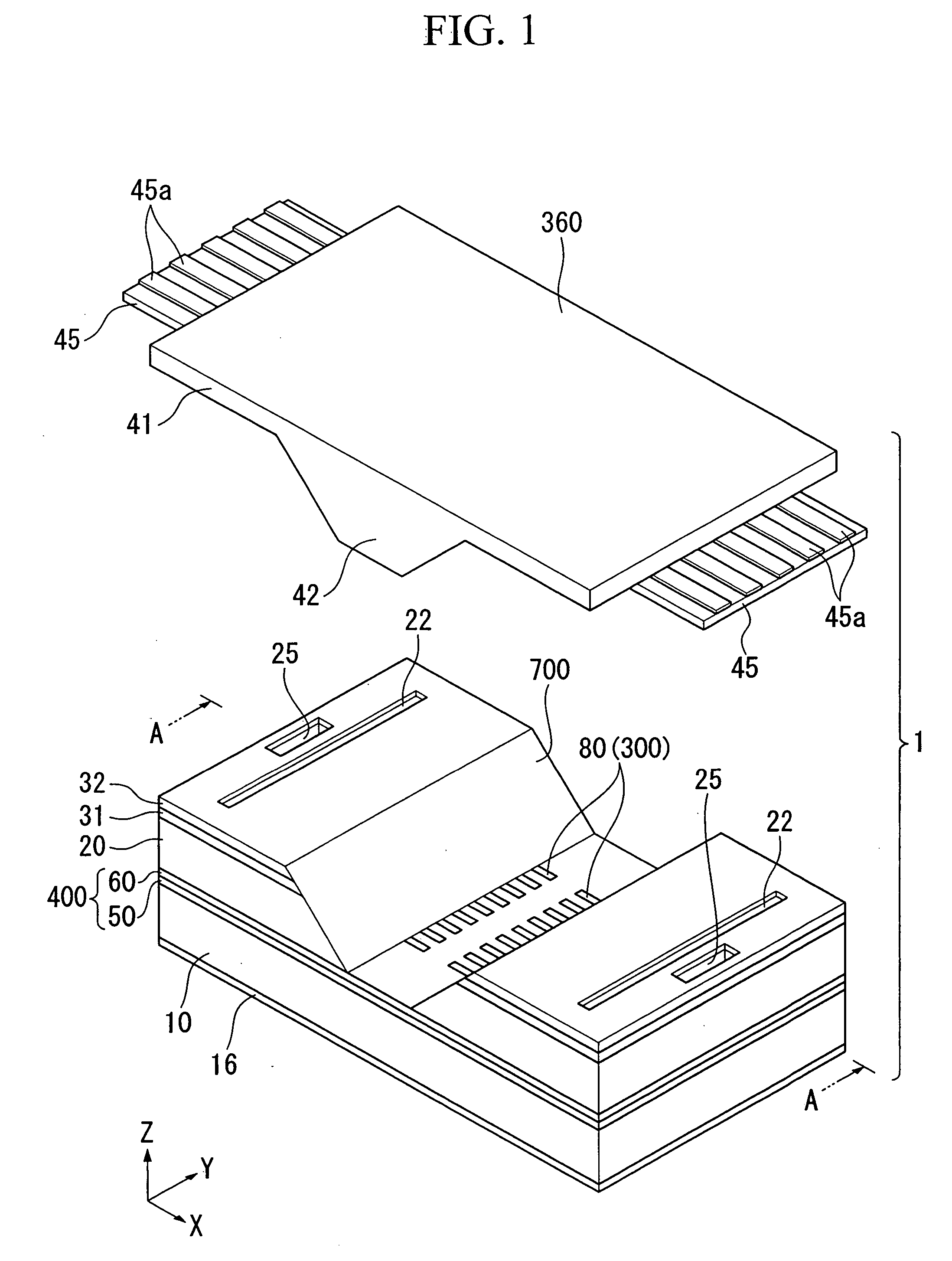
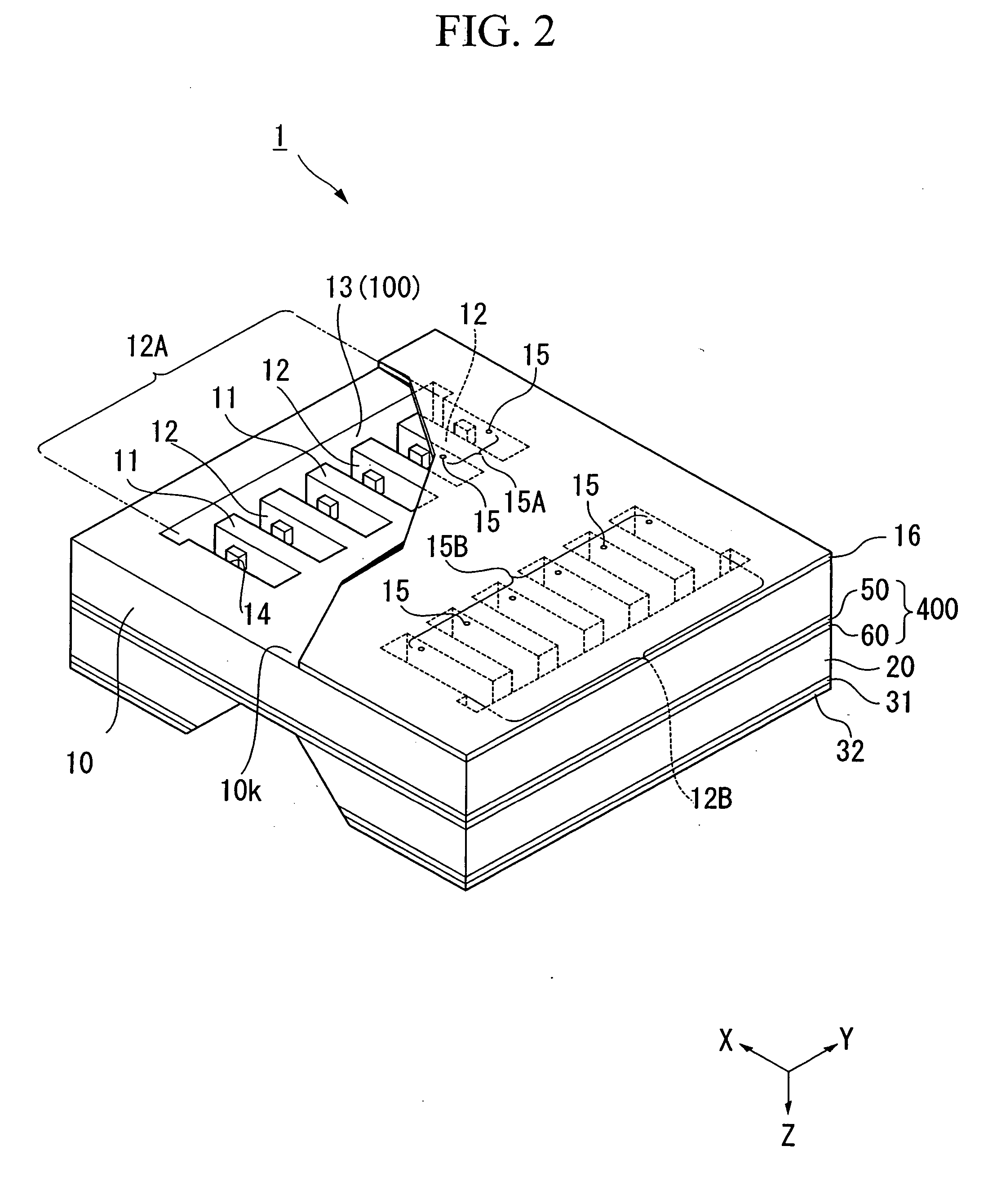
[0158] First, a liquid drop ejection head provided with a device package structure of this invention is explained as a first embodiment of the invention, referring to FIG. 1 through FIG. 4. FIG. 1 is an exploded perspective view showing the first embodiment of a liquid drop ejection head, FIG. 2 is a partial cross-sectional view showing the perspective configuration of a liquid drop ejection head as viewed from below, FIG. 3 is a cross-sectional view along line A-A in FIG. 1, and FIG. 4 is a perspective view of a connector as viewed from the rear side (from below in FIG. 1).

[0159] In the following explanations, an XYZ orthogonal coordinate system is used, and the positional relationships of members are explained by reference to this XYZ orthogonal coordinate system. A prescribed direction in the horizontal plane is taken to be the X direction, the direction in the horizontal plane orthogonal to the X direction is the Y direction, an...

Example

Second Embodiment

[0250] Next, a second embodiment of a liquid drop ejection head, provided with a device package structure of this invention, is explained referring to FIG. 6 through FIG. 8. FIG. 6 is an exploded perspective view showing the embodiment of the liquid drop ejection head, FIG. 7 shows a cross-section of the configuration along line A-A in FIG. 6, and FIG. 8 is an external perspective view of the connector viewed from the rear surface side (the bottom side in FIG. 6).

[0251] In these figures, components which are the same as the constituent components in the first embodiment shown in FIG. 1 through FIG. 5 are assigned the same symbols, and an explanation is omitted.

[0252] As shown in FIG. 8, the connector 360 in this embodiment is provided with a rectangular plate-shape flat plate portion (plate portion) 41, and a connector base member 36a having a protruding portion 42 which protrudes from the flat plate portion 41. Here, the protruding portion 42 protrudes in the −Z...

Example

Third Embodiment

[0273] Next, a third embodiment of a liquid drop ejection head provided with the device package structure of this invention is explained, referring to FIG. 11 through FIG. 13. FIG. 11 is an exploded perspective view showing an embodiment of a liquid drop ejection head, FIG. 12 is a cross-sectional view along line A-A in FIG. 11, and FIG. 13 is a perspective view viewed from the rear-surface side of the connector (the lower side in FIG. 6).

[0274] In these figures, components which are the same as the constituent components in the first embodiment shown in FIG. 1 through FIG. 5 are assigned the same symbols, and an explanation is omitted.

[0275] As shown in FIG. 11 and FIG. 12, a groove portion (depression portion) 700, which is rectangular in shape as viewed from the direction perpendicular to the reservoir formation substrate 20 (the −Z direction), and the x-direction width and Y-direction width of which decrease in moving downward (a quadrangular truncated pyramid...


PUM


Abstract

A device package structure includes: a base body having a depression portion and a conductive connection portion formed in the depression portion; a device having a connection terminal; and a connector having a plate portion having a first surface on which the device is positioned, a protruding portion protruding from the first surface of the plate portion and having a second surface different from the first surface, a terminal electrode formed on the second surface, and a connection wiring electrically connecting the connection terminal of the device and the terminal electrode, wherein the protruding portion of the connector is inserted into the depression portion of the base body, the terminal electrode is connected to the conductive connection portion, and the conductive connection portion is electrically connected to the connection terminal of the device.

Description

CROSS-REFERENCE TO RELATED APPLICATION [0001] This application claims priority to Japanese Patent Application No. 2005-066087, filed Mar. 9, 2005, Japanese Patent Application No. 2005-066088, filed Mar. 9, 2005, Japanese Patent Application No. 2005-066089, filed Mar. 9, 2005, and Japanese Patent Application No. 2005-366243, filed Dec. 20, 2005, the contents of which are incorporated herein by reference. BACKGROUND [0002] 1. Technical Field [0003] The present invention relates to a device package structure, a device packaging method, a liquid drop ejection head, a connector, and a semiconductor device. [0004] 2. Related Art [0005] The wire bonding method is known and widely used as a method of placing and electrically connecting an IC chip or other driver device on a circuit board. For example, as described in Japanese Unexamined Patent Application, First Publication No. 2003-159800 and Japanese Unexamined Patent Application, First Publication No. 2004-284176, technology is disclosed...

Claims


Application Information

Patent Timeline
IPC IPC(8): H01R13/62
CPCB41J2/14233B41J2/17526B41J2202/18B41J2002/14491B41J2/17559B41J2/045
Inventor SATO, EIICHI
Owner SEIKO EPSON CORP
Why Eureka
Try Eureka