A hermetic connector

Pending Publication Date: 2022-09-29
SENIN TECH CORP
View PDF0 Cites 0 Cited by
  • Summary
  • Abstract
  • Description
  • Claims
  • Application Information

AI Technical Summary

Benefits of technology

[0014]According to the present invention, it is possible to realize a hermetic connect

Problems solved by technology

In the above-mentioned hermetic connectors according to the conventional technology, there is a problem that a good sealing cannot be guaranteed because of the bonding defects which could occur by brazing or soldering at the time of manufacturing, the occurrence of crazes by aged deterioration and so on.
In a technology for bonding a metal pin to an insulating substrate by filling glass in the gap and melting it by heating to a high temperature instead of bonding by brazing

Method used

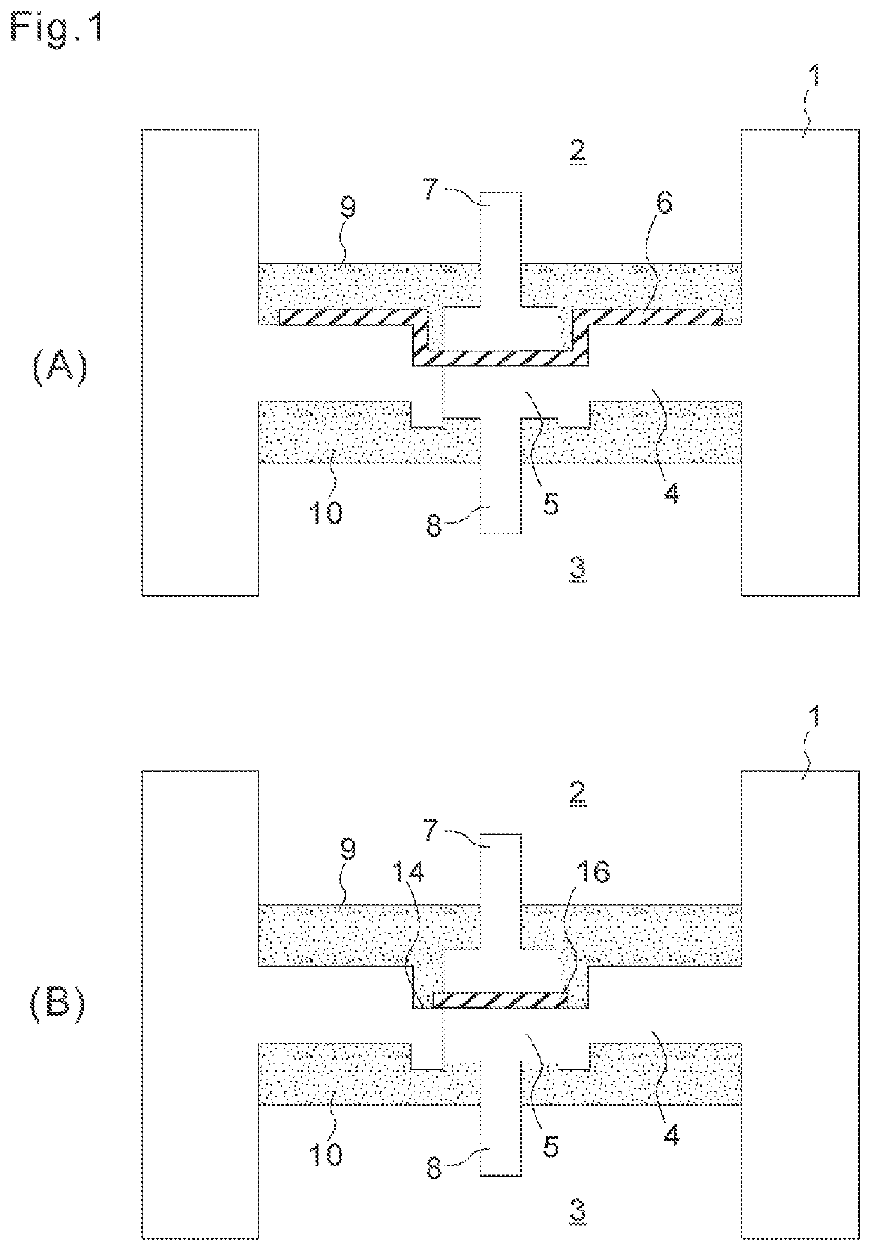
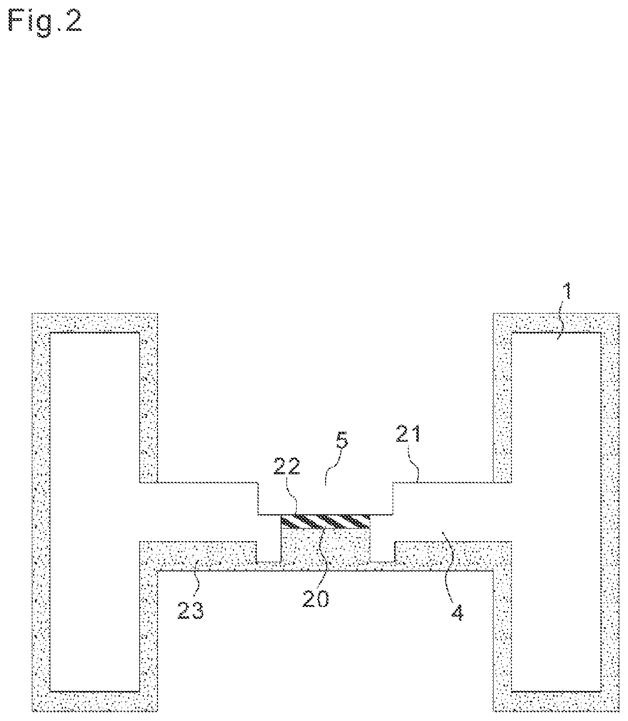
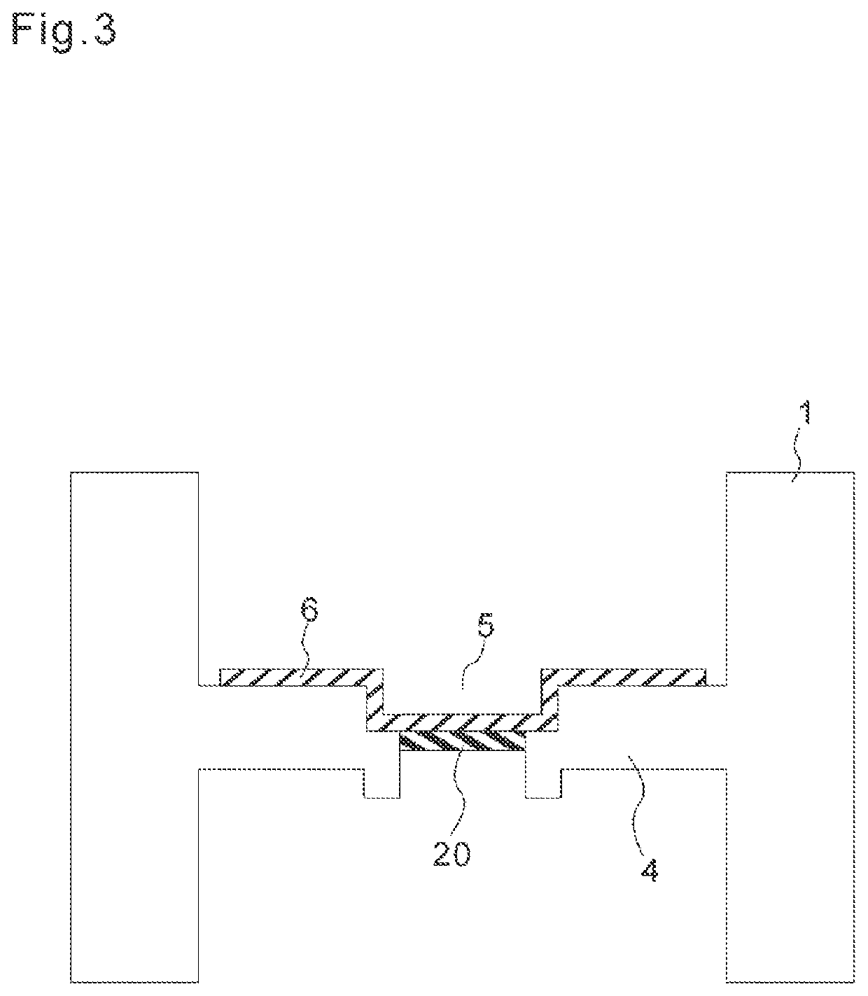

Image

  • A hermetic connector
  • A hermetic connector
  • A hermetic connector

Examples


Example

[0049]In the hermetic connector according to a fourth embodiment of the present invention, as shown in FIG. 9, a plated portion 90 has a shape which is suitable for connecting to components having a rectangular cross section. As shown in FIG. 10, as a connector base portion 100, a partition 101 having a hole 102 is formed. Next, a molded body 103 having a rectangular cross section is formed in the vicinity of the hole 102. A mask layer 104 for patterning is formed by a polylactic acid (PLA) resin or the like on the surface of the connector base portion 100 and the surface of the molded body 103 which are other than the portion where the plated portion 90 is formed.

[0050]A roughening treatment is conducted on the exposed surfaces of the partition 101 and the molded body 103 by etching. The plated portion 90 is formed in a form of a thick film by applying a plating catalyst and conducting an electroless plating and an electroplating. The mask layer 104 is dissolved and removed when th...

Example

[0051]The materials for forming the plated portion in the second through fourth embodiments shown in FIGS. 5-10 are similar to those which are used for forming the plated portion 6 according to the first embodiment. Also, it is possible to form a plated portion having a desired shape, which is other than the shapes shown in the above-mentioned embodiments, corresponding to the components stored in the hermetic connector.

Example

[0052]Next, the configuration of the hermetic connector according to a fifth embodiment of the present invention will be explained referring to FIG. 11. The hermetic connector according to this embodiment is one example of a hermetic coaxial connector having an axial structure which is suitable for transmission of high frequency signals. In FIG. 11, the connector base portion 110 made of an insulating material has an outer partition 111, an intermediate partition 112 and an inner partition 113, and a hole 114 is formed in the central part of the connector base portion 110.

[0053]A plated portion 115 is formed on the surface of the outer wall portion of the connector base portion 110 and the outer partition 111 for connecting to the external conductor of a coaxial cable which is not shown in the drawings. The plated portion 115 is grounded at an appropriate position for providing an electrostatic shield. A plated portion 116 is formed on the hole 114 and a part of the inner partition ...


PUM


Abstract

To realize a hermetic connector structure with a high product yield at a low cost, which prevents leakage certainly. A hole is formed in a partition in an insulating connector base portion, and a conductive portion is adhered to the surface of the partition and formed as an integrated member covering the hole.

Description

TECHNICAL FIELD[0001]The present invention relates to a hermetic connector which can make an electrical connection through a conductive terminal while keeping airtightness.BACKGROUND ART[0002]Conventionally, a miniature electronic component is sealed in a vacuum or non-active gas atmosphere in an airtight manner for preventing corrosion of internal circuits by a high humidity and a malfunction of the internal circuits by changes in viscosity of the gas. A hermetic container is also used for operating electronic components in a vacuum, pressure, liquid or gas environment, and a hermetic connector having a high airtightness is used for introducing power and taking out an internal sensor signal without harming the airtightness of the hermetic container.[0003]Patent Documents 1 and 2 disclose conventional hermetic connectors, wherein a through hole is formed in an insulating substrate, e.g., a ceramic board, a glass epoxy board, or in a metal board, which disconnects an internal atmosph...

Claims


Application Information

Patent Timeline
IPC IPC(8): H01R9/16H01R43/20
CPCH01R9/16H01R43/20H01R4/02H01R13/521H01R13/03
Inventor ITOH, RYO
Owner SENIN TECH CORP
Why Eureka
Try Eureka