Micro LED display panel and preparation method thereof

A display panel and anode technology, which is applied in semiconductor/solid-state device manufacturing, electrical components, electric solid-state devices, etc., can solve the problems of increasing production cost, increasing manufacturing cost, and decreasing production yield, so as to save production cost and improve quality , Improve the effect of production yield

Pending Publication Date: 2021-06-25
BOE TECH GRP CO LTD
View PDF0 Cites 0 Cited by
  • Summary
  • Abstract
  • Description
  • Claims
  • Application Information

AI Technical Summary

Problems solved by technology

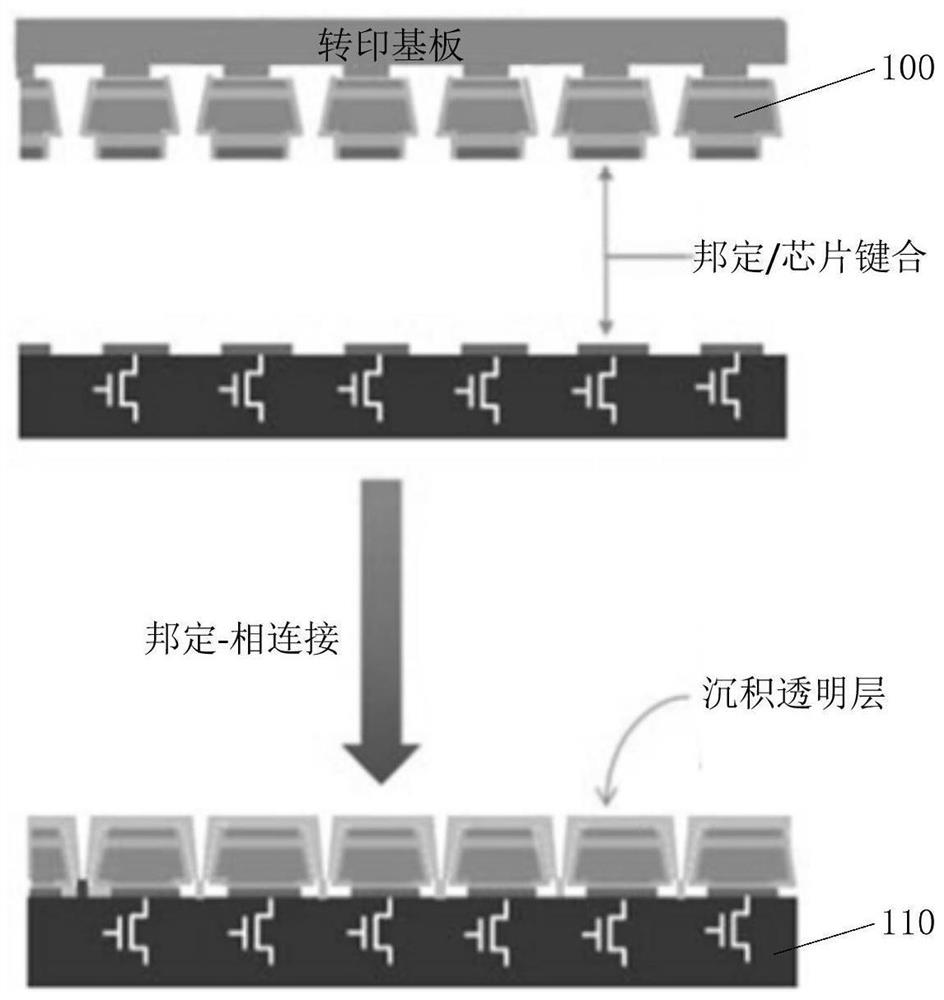
The preparation method of prior art is to form light-emitting diode (diode), needs to carry out high-temperature vapor deposition, needs to use sapphire substrate for this reason, thereby increases manufacturing cost; Moreover, usually each pixel in the display of large area, high resolution uses 1: 1 (Micro-LED) or 1-to-

Method used


Image

  • Micro LED display panel and preparation method thereof
  • Micro LED display panel and preparation method thereof
  • Micro LED display panel and preparation method thereof

Examples


Example Embodiment

[0096] The present application will be described in connection with the embodiments and the drawings below for more clear explanation. The similar components in the drawings are expressed in the same reference numerals. It will be understood by those skilled in the art that the following description is illustrative and not limiting, and the protection range of the present application should not be limited.

[0097] As described in this application, "" "," "is formed on ...", "can indicate that the one layer is directly formed or disposed on the other layer, or the one layer is indirectly formed or Set on the other layer, that is, there is still other layers between the two layers.

[0098] It should be noted that, although the term "first", "second", the like can be used herein, such as various components, components, elements, regions, layers, and / or portions, but these components, components, components, regions, layers And / or part should not be limited by these terms. Inste...


PUM


Abstract

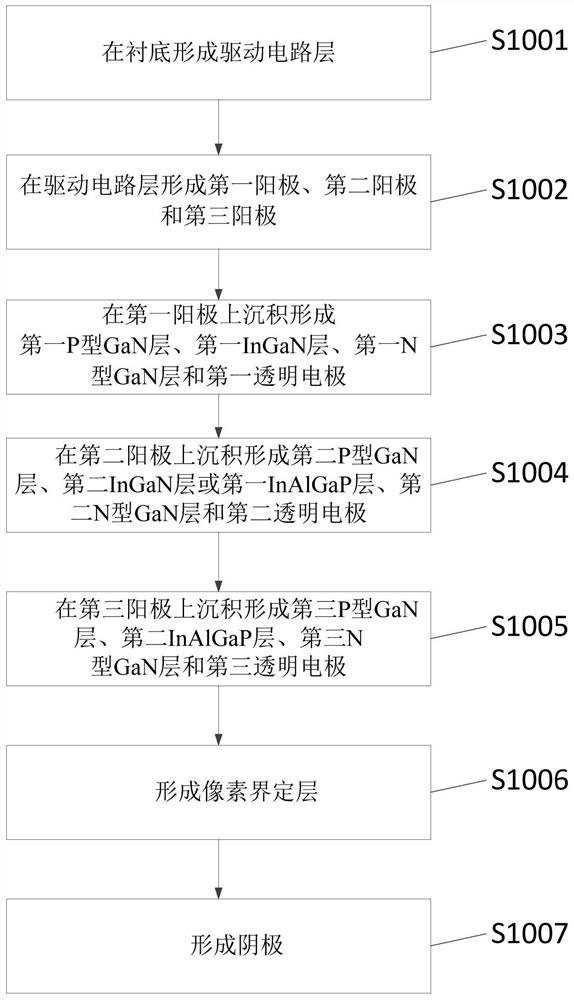
The embodiment of the invention discloses a micro LED display panel and a preparation method thereof. In one specific embodiment, the method comprises the steps of forming a driving circuit layer; forming a first anode, a second anode and a third anode; sequentially depositing a first P-type GaN layer, a first InGaN layer, a first N-type GaN layer and a first transparent electrode on the first anode; sequentially depositing a second P-type GaN layer, a second InGaN layer or a first InAlGaP layer, a second N-type GaN layer and a second transparent electrode on the second anode; sequentially depositing a third P-type GaN layer, a second InAlGaP layer, a third N-type GaN layer and a third transparent electrode on the third anode; forming a pixel defining layer; and forming a cathode. According to the embodiment, a high-temperature evaporation means required for preparing the micro-LED in the prior art can be avoided, the manufacturing yield of the micro-LED display panel can be increased, and the quality of the micro-LED display panel can be improved.

Description

technical field [0001] This application relates to the field of display technology. More specifically, it relates to a micro-LED display panel and a preparation method thereof. Background technique [0002] Micro-LED Display (miniature light-emitting diode display) due to its advantages of ultra-high pixels, ultra-high resolution, high brightness, low power consumption, stable material performance, long life and no image burn-in, its performance is much higher than that of existing LCD (Liquid Crystal Display, Liquid Crystal Display) and OLED (Organic Light-Emitting Diode, Organic Light-Emitting Diode), therefore, are widely used in fields such as micro-projection, transparent display, and head-up display. [0003] Usually displays made of Micro-LED or QNED etc. cut the nano-scale color LED (light-emitting diode) 100 made on the sapphire substrate into micron-scale size, and then cut them on the glass substrate or PI (Polyimide, polyimide) It is made by transfer on the act...

Claims


Application Information

Patent Timeline
IPC IPC(8): H01L27/15H01L33/00H01L21/84
CPCH01L21/84H01L27/156H01L33/0075
Inventor 宋泳锡李禹奉
Owner BOE TECH GRP CO LTD
Why Eureka
Try Eureka