Image forming apparatus

a technology of forming apparatus and forming plate, which is applied in the direction of electrographic process apparatus, instruments, optics, etc., can solve the problems of affecting the quality of the image, the inability to measure in advance the print, and the shifted print of the toner image on the recording paper. achieve the effect of simple setting operation

Active Publication Date: 2012-11-01
SHARP KK
View PDF5 Cites 2 Cited by
  • Summary
  • Abstract
  • Description
  • Claims
  • Application Information

AI Technical Summary

Benefits of technology

[0016]The present invention was made in consideration of the above-described situation, and it is an object thereof to provide an image forming apparatus capable of appropriately correcting the print position of the toner image on the recording papers with simple setting operation, regardless of the number of paper feed cassettes or the type of recording papers.

Problems solved by technology

Further, shifted print of the toner image on the recording paper occurs due to various causes and is not constant.
However, in large-scale image forming apparatuses, the number of paper feed cassettes is large and it is not easy to measure in advance the print position of the toner image on the recording papers with respect to each paper feed cassette.
Moreover, even when the same paper feed cassette is used, the print position of the toner image on the recording papers varies, and so even if the print position of the toner image on the recording papers is measured with respect to each paper feed cassette, the measured values are not very reliable.
Accordingly, even if the print position of the toner image on the recording papers is corrected based on the measured value with respect to each paper feed cassette, the correction is not always appropriate.
Furthermore, it is also not easy to obtain in advance the print position adjustment value with respect to each type of recording papers as in Patent Literature 1.
Accordingly, even if the adjustment value for the print position of the toner image on the recording papers is obtained with respect to each type of recording papers, those adjustment values are not very reliable.
Therefore, even if the print position of the toner image on the recording paper is corrected in accordance with the adjustment value for each type of recording papers, the print position of the toner image is not always corrected appropriately.
Of course if the print positions of the toner image on a plurality of recording papers are measured with respect to the same paper feed cassette or the same type of recording papers and the average value of those measured values is obtained, the measured values or adjustment values would be more reliable However, it is extremely difficult to perform such operation with respect to each of the plurality of the paper feed cassettes or multiple types of recording papers.
Further, even if the time taken for the leading end of recording papers to reach the transfer position of the toner image from the registration roller is made constant by controlling the rotational speed of the registration roller as in Patent Literature 2, such control of the rotational speed of the registration roller becomes difficult as the transport speed of recording papers is accelerated and the rotational speed of the registration roller is also accelerated.

Method used


Image

  • Image forming apparatus
  • Image forming apparatus
  • Image forming apparatus

Examples


Embodiment Construction

[0053]An embodiment of the present invention will be described in detail with reference to the accompanying drawings.

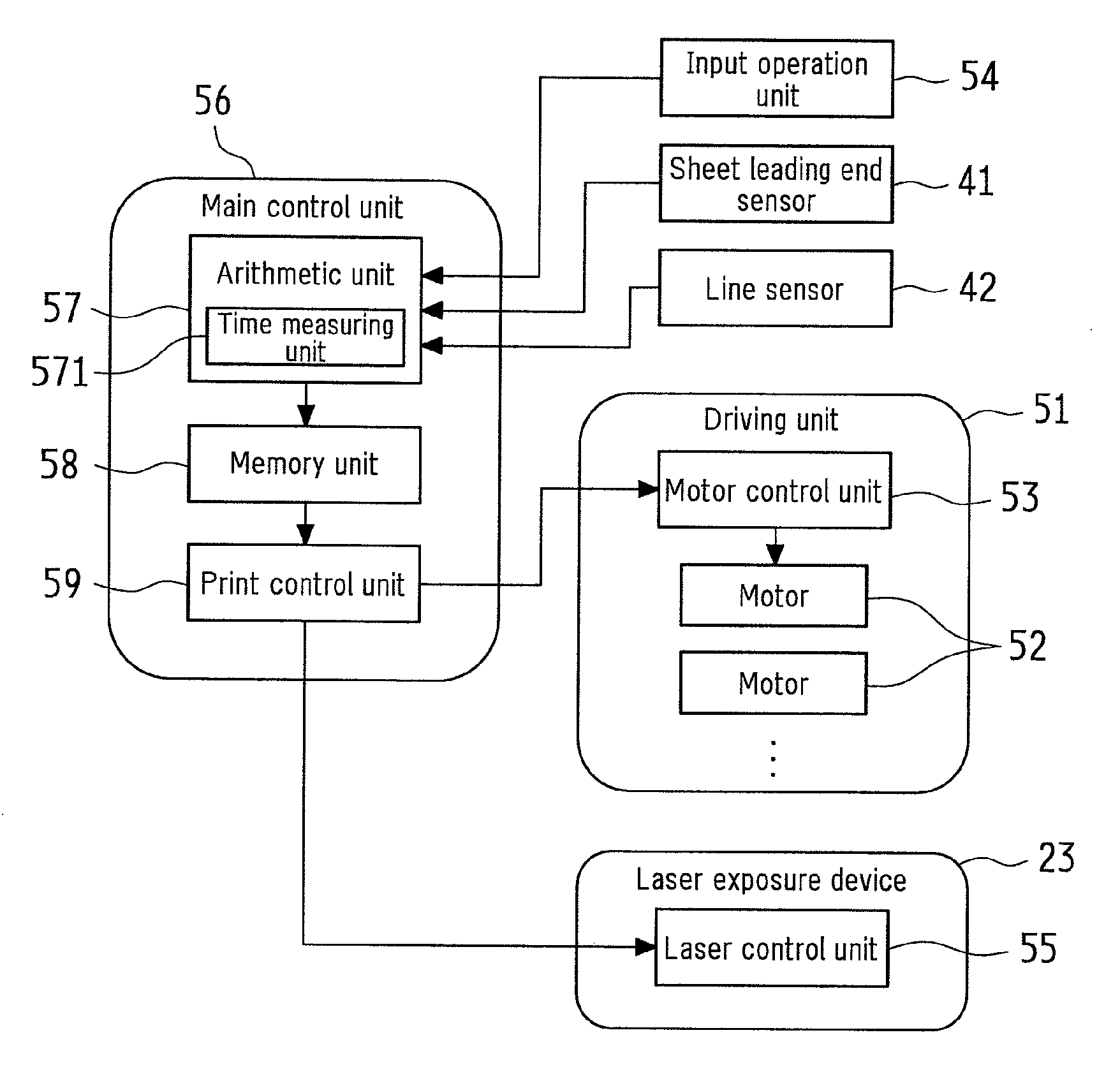
[0054]FIG. 1 is a cross-sectional view showing an embodiment of the image forming apparatus according to the present invention. An image forming apparatus 1 according to the present embodiment is designed to print a monochrome image given by image data on a recording paper, and broadly divided into a print unit 11, a sheet transport unit 12, and a paper supply unit 13.

[0055]In this image forming apparatus 1, image data is received from an external scanner, a terminal device or the like, subjected to various kinds of image processing, and input to the print unit 11, and an image given by the image data is printed on a recording paper in the print unit 11.

[0056]A photosensitive drum 21 is arranged in an approximate center of the print unit 11, and in its surroundings a charging device 22, a laser exposure device 23, a developing device 24, a transfer roller 25, and a cl...


PUM


Abstract

The image forming apparatus includes: a paper feed unit; a print unit; a registration roller; a sheet leading end sensor provided downstream, in a transport direction of the recording paper, of the registration roller; a time measuring unit for measuring a time from a start point of transportation of the recording paper by the registration roller to a point of detection of the leading end of the recording paper by the sheet leading end sensor; a memory unit for storing a reference image forming time and a reference time; a print control unit; and an arithmetic unit for obtaining a difference between the reference time and the time detected by the time measuring unit. The print control unit adjusts the length of the image forming period in accordance with the adjusted image forming time determined based on the difference obtained by the arithmetic unit and the reference image forming time.

Description

CROSS-REFERENCE TO RELATED APPLICATION[0001]This application claims priority under 35 U.S.C. §119(a) on Patent Application No. 2011-098298 filed in Japan on Apr. 26, 2011, the entire contents of which are herein incorporated by reference.BACKGROUND OF THE INVENTION[0002]1. Field of the Invention[0003]The present invention relates to an image forming apparatus for correcting the print position of an image on recording papers to prevent shifted print of the image.[0004]2. Description of the Related Art[0005]In this kind of image forming apparatuses, an image carrier surface is uniformly charged and scanned with a light beam, and an electrostatic latent image is formed on the image carrier surface. The electrostatic latent image on the image carrier surface is developed, forming a toner image on image carrier surface. Then, the toner image is transferred from the image carrier surface onto a recording paper, the recording paper is headed and pressed, and the toner image is fixed on the...

Claims


Application Information

Patent Timeline
Patent Type & Authority Applications(United States)
IPC IPC(8): G03G15/00
CPCG03G15/6564G03G2215/00569G03G2215/00599G03G15/6561G03G2215/00734G03G2215/00742G03G15/235G03G2215/00721
Inventor TOMITA, NORIOFUKADA, YASUAKIATSUMI, HIDETOSHIWAKAMOTO, KOJIOGO, ATSUSHISAKAI, RYOSUKE
Owner SHARP KK
Why Eureka
Try Eureka