
Scanning Multispectral Telescope Comprising Wavefront Analysis Means

Active Publication Date: 2012-11-08
THALES SA
View PDF1 Cites 2 Cited by
  • Summary
  • Abstract
  • Description
  • Claims
  • Application Information

AI Technical Summary

Benefits of technology

[0026]The device according to the invention makes it possible to apply the wavefront analysis by phase diversity methods to multispectral detection, this making it possible to obtain quality images in a plurality of spectral bands at the price of minor modifications to the optical architecture of the telescope or its detection assembly.

Problems solved by technology

Now, these instruments are capable only of measuring a light intensity and the phase information of the image is therefore lost.
The drawback with such an approach is the use of a portion of the input flux for an “ancillary” analysis channel, as well as the complexity of the optical device that has to be put in place.

Method used


Image

  • Scanning Multispectral Telescope Comprising Wavefront Analysis Means
  • Scanning Multispectral Telescope Comprising Wavefront Analysis Means
  • Scanning Multispectral Telescope Comprising Wavefront Analysis Means

Examples


Embodiment Construction

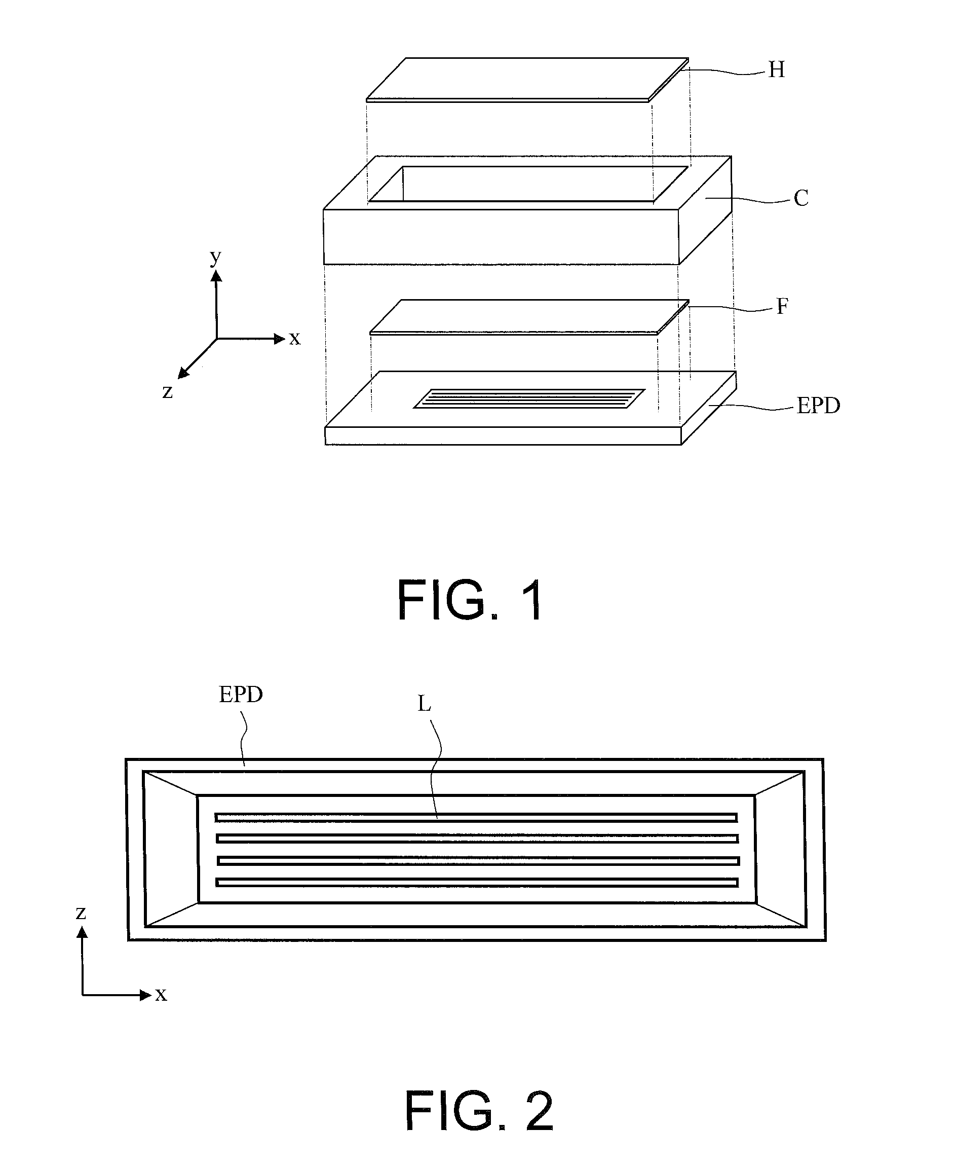
[0042]As has been stated, a scanning multispectral telescope comprises a photodetection assembly. The latter comprises a number of parallel rows of photodetectors, each row being dedicated to a particular spectral band, each spectral band being centred on a mean wavelength, the rows all being situated in a same plane.

[0043]In the prior art devices, a same multispectral image line is perfectly focused on the rows of photodetectors. The plane of the photoreception rows and the image plane are one and the same.

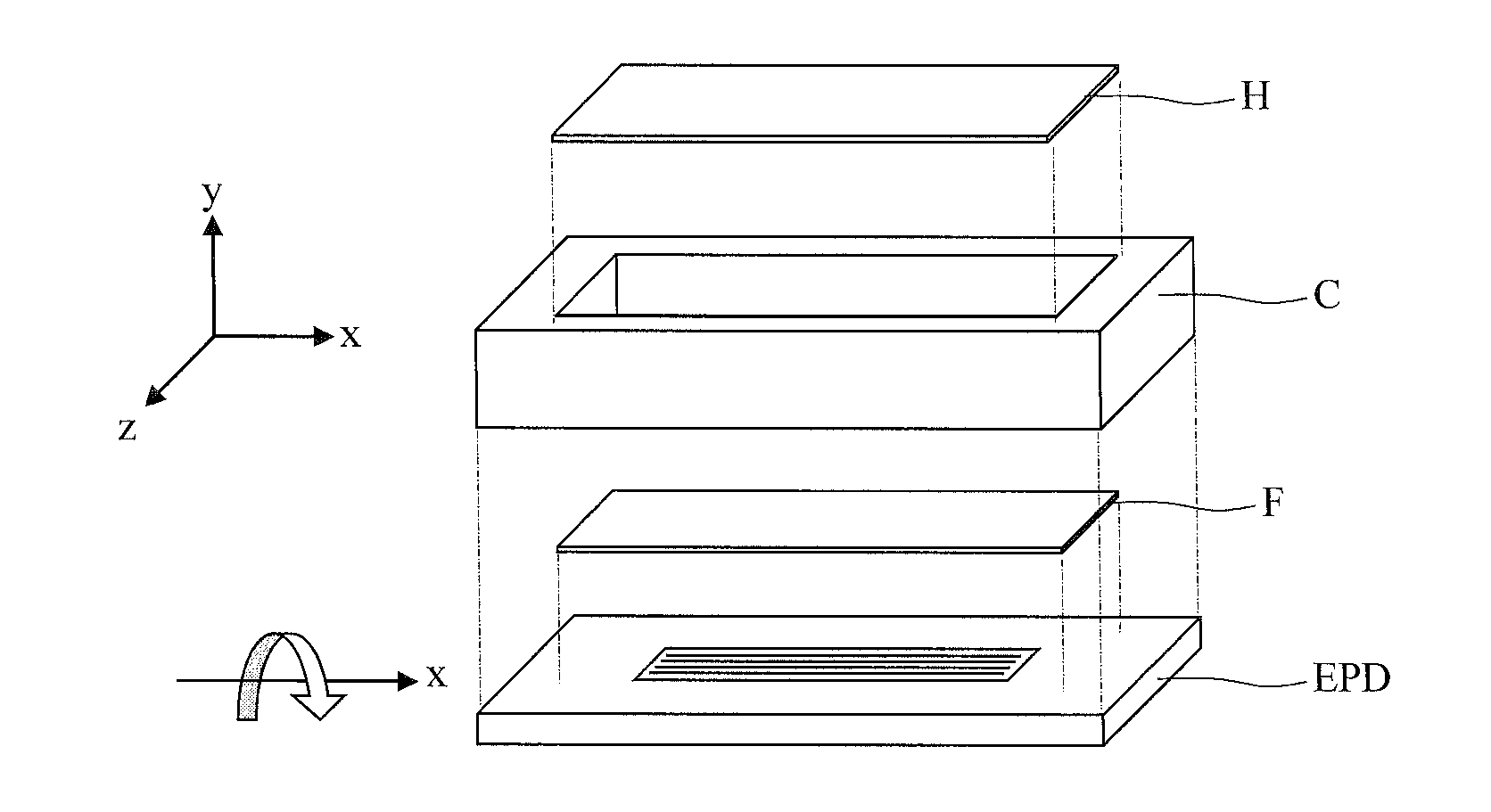
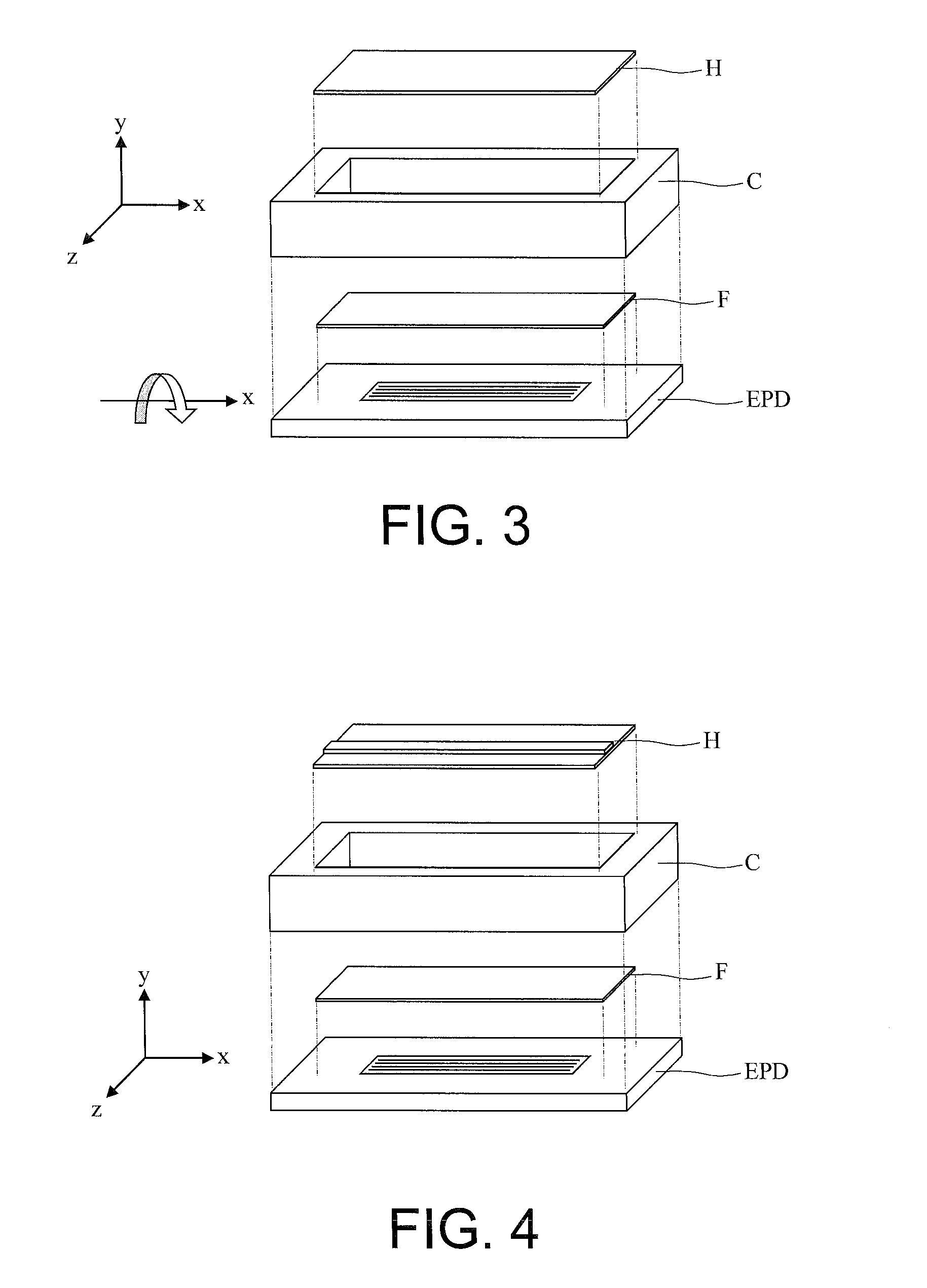
[0044]In the device according to the invention, the telescope comprises optical or mechanical means arranged in such a way that at least one of the rows of photodetectors is offset by a fraction of the mean wavelength which corresponds to it on an axis perpendicular to the image plane.

[0045]Thus, it becomes possible to carry out, in parallel with the spectral analysis, an analysis of the wavefront given by the optics of the telescope by using the phase diversity analysis methods ...


PUM


Abstract

A scanning multispectral telescope comprises an optical architecture arranged so as to focus the image of an object in the vicinity of a photodetection assembly, the area of focus being an image plane. The photodetection assembly comprises a number of parallel rows of photodetectors, each row being dedicated to a particular spectral band, each spectral band being centred on a mean wavelength. The telescope comprises means for acquiring and analyzing the images obtained from the rows of photodetectors using a phase diversity algorithm. Finally, the telescope comprises optical or mechanical means arranged in such a way that at least one of the rows of photodetectors is offset by a fraction of the mean wavelength which corresponds to it on an axis perpendicular to the image plane.

Description

CROSS-REFERENCE TO RELATED APPLICATION[0001]This application claims priority to foreign French patent application No. FR 1101390, filed on May 5, 2011, the disclosure of which is incorporated by reference in its entirety.FIELD OF THE INVENTION[0002]The general field of the invention is that of the analysis or photoreception devices of scanning space optical instruments providing a multispectral analysis.BACKGROUND[0003]A space optical instrument or space telescope comprises a focusing optical system generally comprising a number of mirrors and an image analysis device comprising photoreception means and computing means so as to be able to process the images received. FIG. 1 represents an exploded view of the photoreception means, essentially comprising a photodetection assembly EPD, a filter F, a rack B and a protection window H. When the photoreception assembly is intended to carry out spectral analysis, it includes a suitable image analysis device capable of providing images in di...

Claims


Application Information

Patent Timeline
IPC IPC(8): G01J1/42
CPCG01J9/00
Inventor PERRIN, GUILLAUMEBERNOT, MARCFALZON, FREDERICLIOTARD, ARNAUD
Owner THALES SA
Learn More