
Liquid crystal display panel

a display panel and liquid crystal technology, applied in static indicating devices, instruments, non-linear optics, etc., can solve the problems of leakage of confidential information, inconvenience to users, and affect the optical characteristic and display quality of front view display panels, so as to achieve optimal display quality

Active Publication Date: 2012-11-08
OPTRONIC SCI LLC
View PDF4 Cites 15 Cited by
  • Summary
  • Abstract
  • Description
  • Claims
  • Application Information

AI Technical Summary

Benefits of technology

"The patent is about a liquid crystal display (LCD) panel that offers both an anti-peep effect and optimal display quality without sacrificing the aperture ratio or adding any additional viewing angle control modules. The panel has a pixel structure designed with sub-pixels that have different liquid crystal alignments and driving voltages to achieve the desired display quality and anti-peep effect. The panel also has different luminous flux in the upper and lower half viewing angles, and the driving voltage of the first pixel electrode areas is lower than the second pixel electrode areas when displaying the first front view luminosity. Overall, the panel provides a better display quality and anti-peep effect without compromising the aperture ratio or requiring additional viewing angle control modules."

Problems solved by technology

However, in some cases (for example, when confidential information is read or a password is input), the wide viewing angle display effect may cause confidential information to be peeped by others and accordingly leak of the confidential information.
However, because an additional optical film is used, the front view optical characteristic and display quality of the display panel are affected.
Besides, this technique brings inconvenience to the user as the anti-peep film has to be manually attached and removed.
However, in an actual application, it is impossible to obtain a completely collimated light due to the difficulty in optical path control.
Even though this technique can reduce the distribution of backlight at large viewing angles, it cannot reduce the brightness at the large viewing angles to an unrecognizable extent.
Thus, this technique does not provide a satisfying anti-peep effect.
However, because an additional module is adopted, the weight and thickness of the entire display are doubled, and the hardware cost thereof is also increased.

Method used


Image

  • Liquid crystal display panel
  • Liquid crystal display panel
  • Liquid crystal display panel

Examples


Embodiment Construction

[0040]Reference will now be made in detail to the present preferred embodiments of the disclosure, examples of which are illustrated in the accompanying drawings. Wherever possible, the same reference numbers are used in the drawings and the description to refer to the same or like parts.

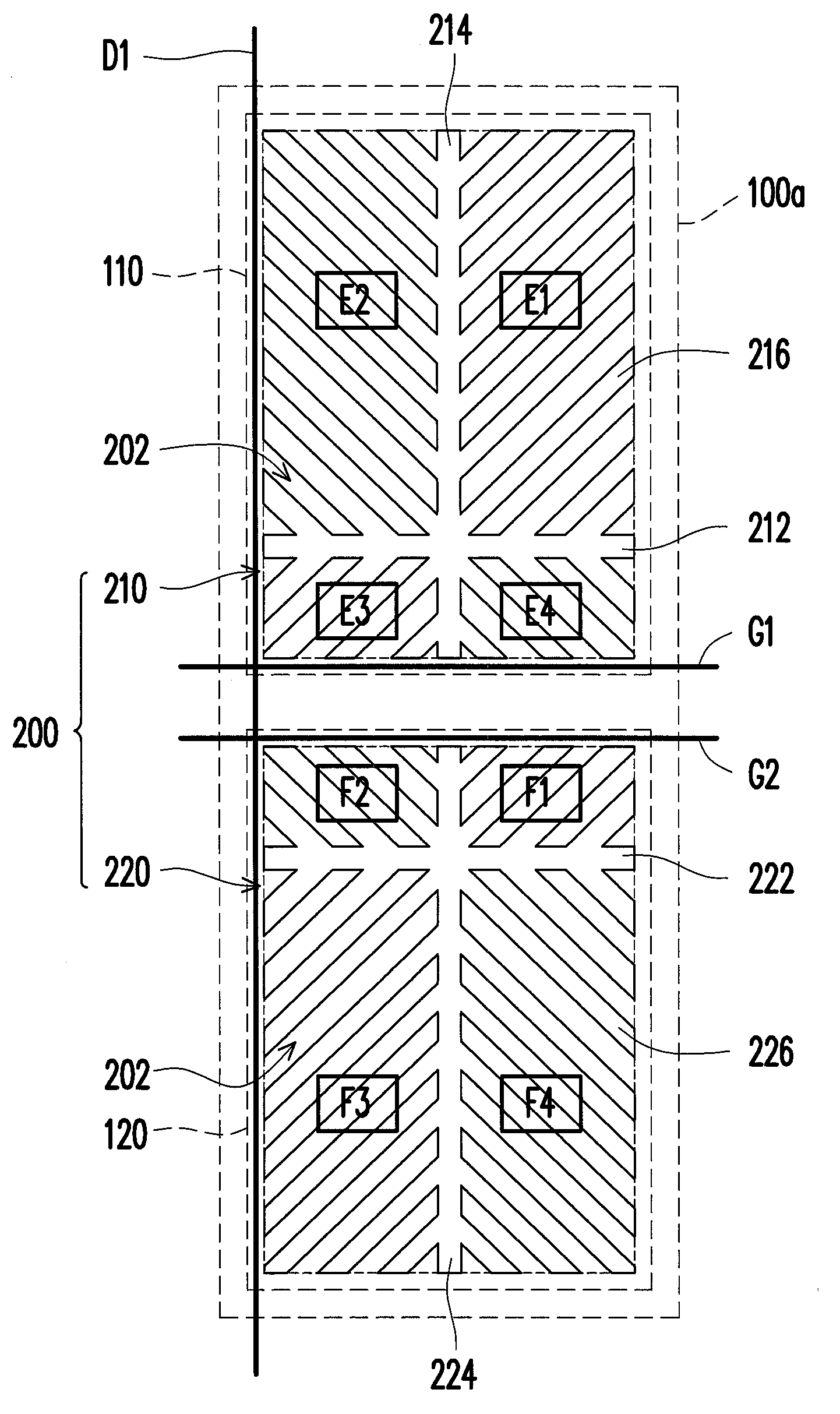
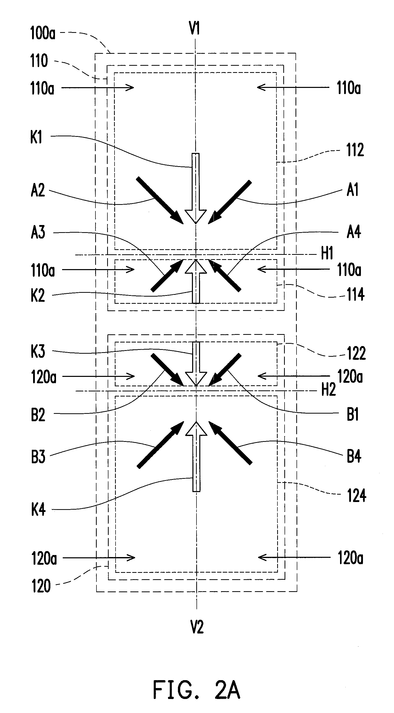
[0041]In a liquid crystal display (LCD) panel provided by the disclosure, each sub-pixel is divided into a first pixel electrode area and a second pixel electrode area. Each pixel electrode area is given an asymmetric viewing angle characteristic, but the two pixel electrode areas are mirror symmetric to each other along a predetermined axis. Thus, when the LCD panel is in a wide viewing angle display mode, both the first pixel electrode area and the second pixel electrode area of each sub-pixel contribute luminosity. Thus, when the first pixel electrode areas and the second pixel electrode areas are all enabled, the LCD panel offer the same symmetric pixel characteristic as a regular display, and a...


PUM

PropertyMeasurementUnit
angleaaaaaaaaaa
azimuthal angleaaaaaaaaaa

Abstract

A liquid crystal display (LCD) panel is provided. A pixel structure of the LCD panel has an asymmetrical liquid crystal alignment. The LCD panel is divided into an array of display blocks. When the LCD panel is in a narrow viewing angle display mode, some of the display blocks are disabled or darkened so that a displayed image is interfered by the disabled or darkened display blocks when it is viewed from the side. Thereby, an anti-peep effect is achieved.

Description

CROSS-REFERENCE TO RELATED APPLICATION[0001]This application claims the priority benefit of Taiwan application serial no. 100115621, filed on May 4, 2011. The entirety of the above-mentioned patent application is hereby incorporated by reference herein and made a part of this specification.BACKGROUND OF THE DISCLOSURE[0002]1. Field of the Disclosure[0003]The disclosure generally relates to a liquid crystal display (LCD) panel, and more particularly, to a LCD panel offering an anti-peep effect.[0004]2. Description of Related Art[0005]A display usually offers a wide viewing angle display effect in order to allow multiple viewers to view the displayed images. However, in some cases (for example, when confidential information is read or a password is input), the wide viewing angle display effect may cause confidential information to be peeped by others and accordingly leak of the confidential information. Thus, in order to satisfy both requirements mentioned above, displays switchable b...

Claims


Application Information

Patent Timeline
Patent Type & Authority Applications(United States)
IPC IPC(8): G02F1/1337
CPCG02F1/1323G02F1/134336G02F2001/134345G02F1/133G09G2358/00G02F1/1343G09G2300/0447G09G2320/068G02F1/1337G02F1/134345
Inventor YEH, CHAO-WEILIAO, CHIEN-HUANGHSU, WEN-HAO
Owner OPTRONIC SCI LLC
Learn More