Spatial resolution enhancements in multibeam confocal scanning systems

Inactive Publication Date: 2012-11-08
VISITECH INT
View PDF1 Cites 22 Cited by
  • Summary
  • Abstract
  • Description
  • Claims
  • Application Information

AI Technical Summary

Benefits of technology

[0025]The ability to collect the intensity data in parallel from multiple ROIs when using multi beam scanners significantly improves the speed of image (i.e. data) capture. The ability of modern computer systems with parallel oper

Problems solved by technology

Such confocal images are substantially limite

Method used


Image

  • Spatial resolution enhancements in multibeam confocal scanning systems
  • Spatial resolution enhancements in multibeam confocal scanning systems
  • Spatial resolution enhancements in multibeam confocal scanning systems

Examples


Example

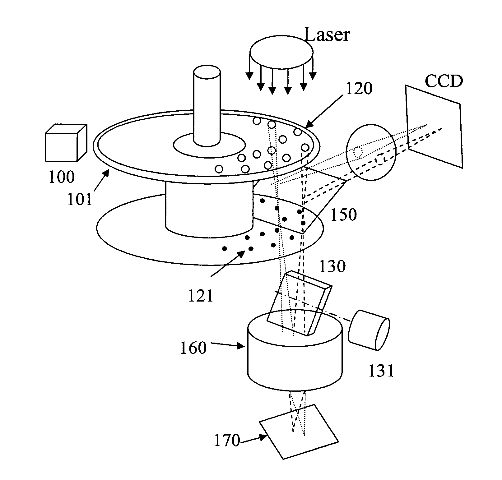
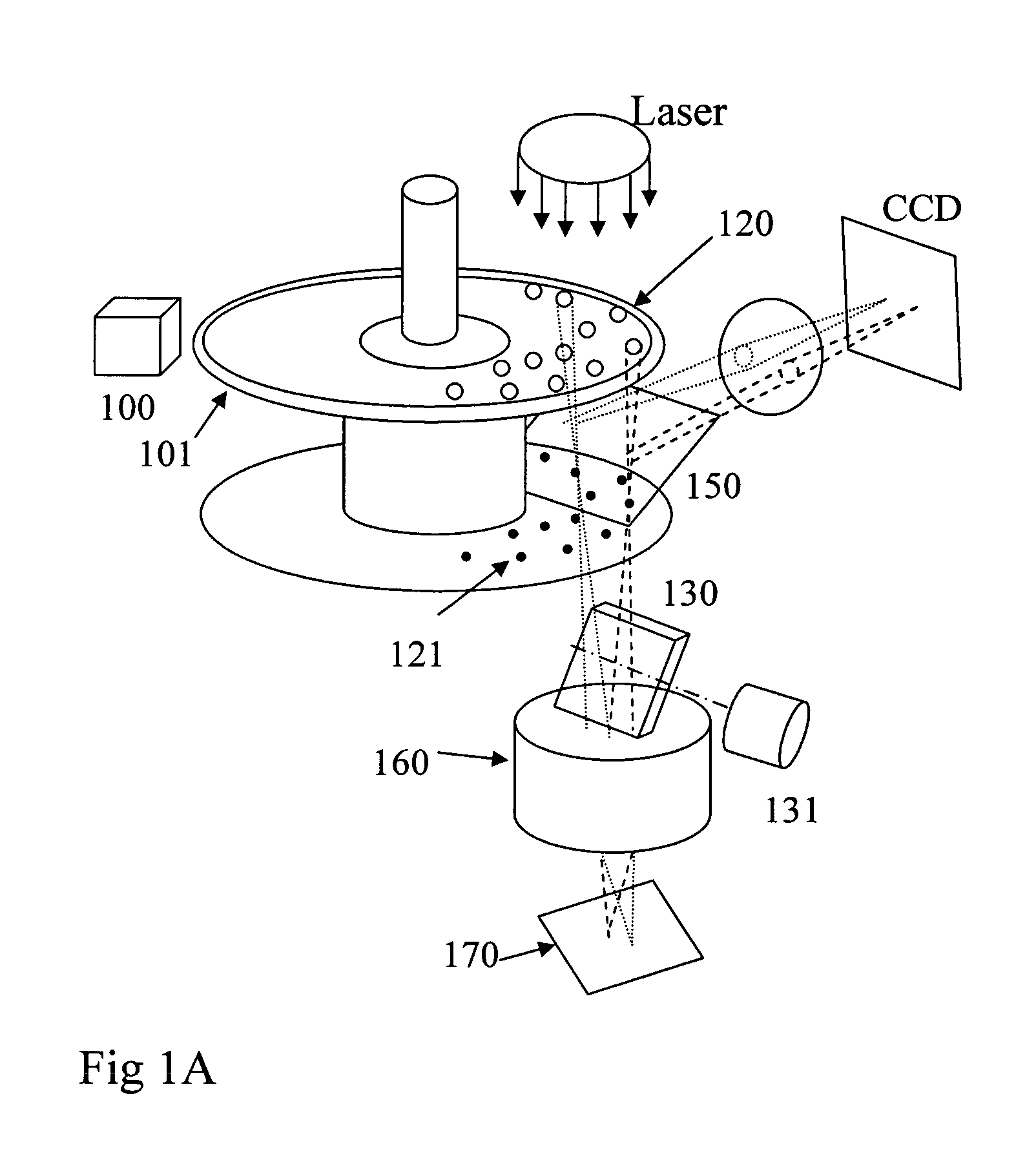
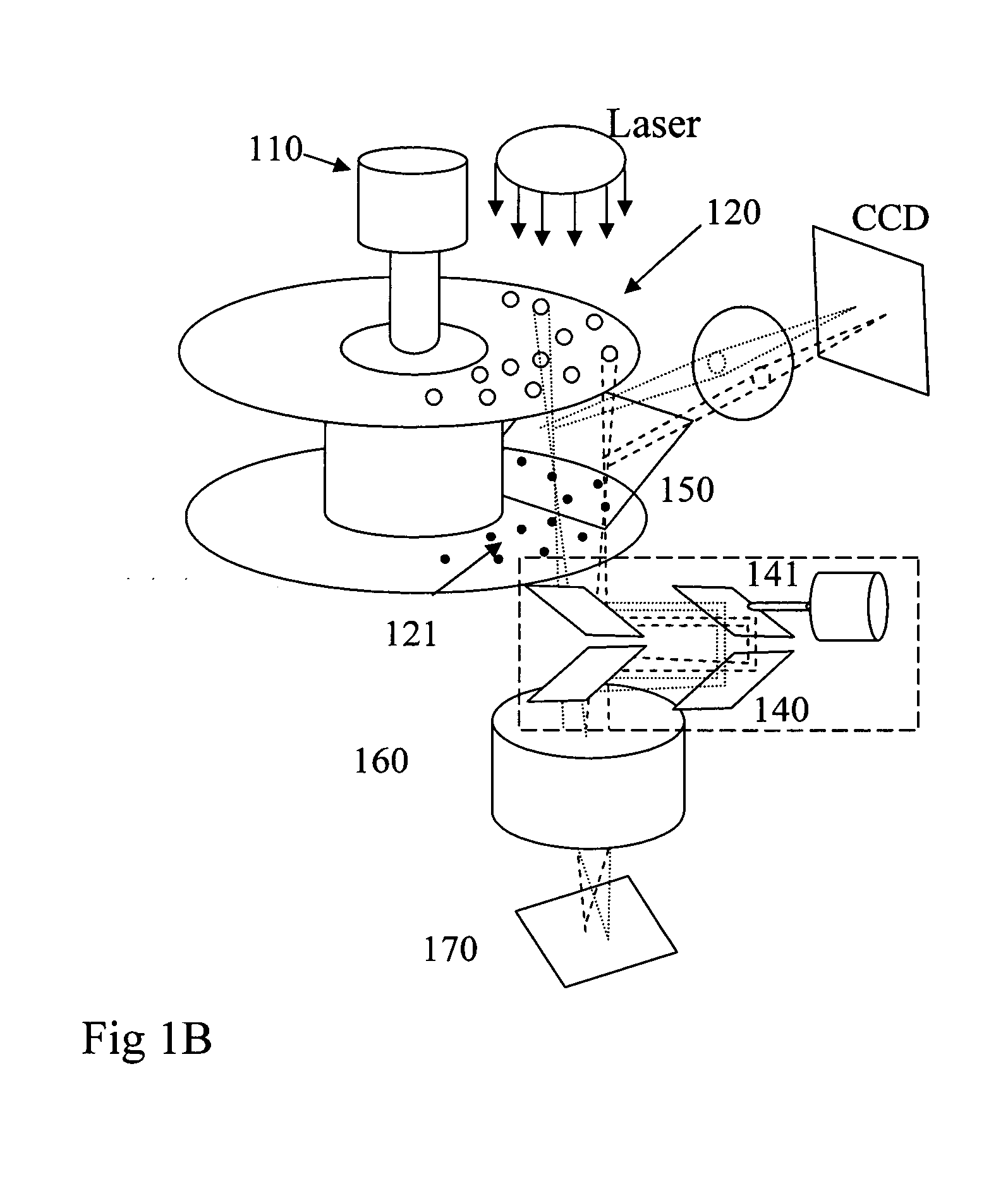
[0037]In a typical Nipkow disc configuration (FIGS. 1A and 1B) an expanded laser beam illuminates the field of view of the sample 170 after passing through a microlens array disc 120, a dichroic mirror 150 mounted between the microlens and pinhole discs, a pinhole array disc 121 and the microscope optics 160. The matching patterns of microlenses on 120 and pinholes on 121 are constructed as a number of interleaved spiral patterns (FIG. 2B) where the separation distance 210 between the start and end of one spiral is filled with N other identical spirals. Therefore in one rotation of the discs, the image is scanned N times. The microlenses and pinholes are typically arranged on the spirals such that the separation distance between them along the spiral is the same as the separation distance between spirals to maintain a uniform area density of microlenses and pinholes. The positions of the microlenses and pinholes on each spiral can be described by the polar coordinates r,phi (FIG. 2B...


PUM


Abstract

The invention relates to improving the spatial resolution of images captured using multi-beam scanning confocal imaging systems by developing the mechanisms required in a variety of multibeam confocal scanner formats that enable the data capture requirements of the prior art calculations to be met.

Description

TECHNICAL FIELD[0001]The present invention relates to improving the spatial resolution of images captured using multi-beam scanning confocal imaging systems by developing the mechanisms required in a variety of multi-beam confocal scanner formats that enable the data capture requirements of the prior art calculations to be met.DESCRIPTION OF THE PRIOR ART[0002]Attempts at improving spatial image resolution beyond the Abbe resolution limit in wide field and confocal imaging systems have used structured illumination methods combined with manipulation of the Fourier representation of those images (Mueller and Enderlein, Physical Review Letters 104, 198101 (2010)). These attempts have been targeted at traditional single beam scanning confocal systems and have not been applied to multi-beam confocal scanning systems because the latter systems do not inherently contain the necessary elements or the precision of step by step scanning or synchronisation between elements to obtain the data r...

Claims


Application Information

Patent Timeline
IPC IPC(8): H04N1/04
CPCG02B21/0044G02B27/58G02B21/0072G02B21/0048
Inventor SHEBLEE, JAFERCOLEMAN, STEVEN
Owner VISITECH INT
Why Eureka
Try Eureka