

Resolution-Enhanced Plenoptic Imaging System
- Summary
- Abstract
- Description
- Claims
- Application Information
AI Technical Summary
Benefits of technology
Problems solved by technology
Method used
Image

Examples
example pif
BASED ON GEOMETRICAL OPTICS
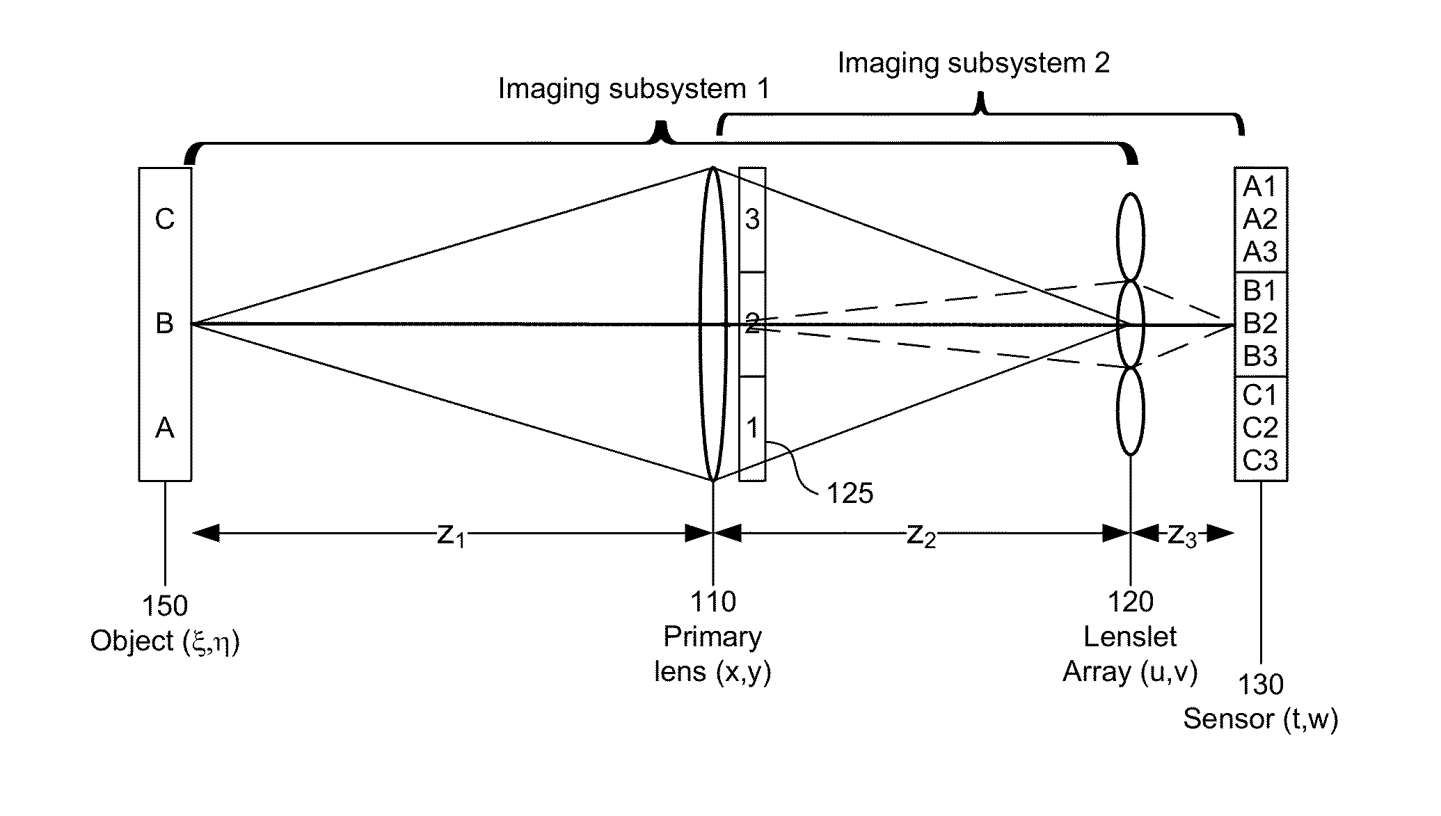
[0081]This derivation uses the nomenclature shown in FIG. 1 and the corresponding text. For convenience, the following derivation is one-dimensional. The extension to two dimensions is straightforward. The following definitions are also used:
[0082]λ Design wavelength
[0083]D Diameter of primary lens 110
[0084]F Focal length of primary lens 110
[0085]d Diameter of microlens 120
[0086]f Focal length of microlens 120
[0087]k Lenslet counter
[0088]R Radius of curvature of concave microlens surface
[0089]t Thickness of microlens
[0090]n Refractive index of microlens
[0091]W Sensor size
[0092]Δp Size of sensor pixel
[0093]δx Sampling interval in the object plane
[0094]2M Number of object samples
[0095]One geometrics optics approach is based on ray trace matrices. The basic ray trace matrix for the plenoptic imaging system of FIG. 1 is given by
S[z3]L[-1f]{tck}S[z2]L[-1F]{tp*}S[z1](B1)
where S[ ] is the matrix for free space propagation and L[ ] is the matrix for propagation th...
PUM
 Abstract
Description
Claims
Application Information